Asus Z97-A User Guide - Page 77
DIGI+ VRM, Channel A/B DIMM Control [Enable Both DIMMs], Scrambler Setting [Optimized ASUS]
 |
View all Asus Z97-A manuals
Add to My Manuals
Save this manual to your list of manuals |
Page 77 highlights
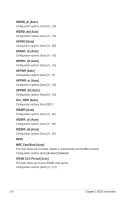
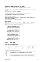
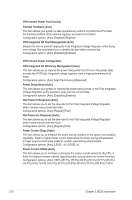
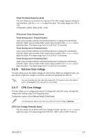
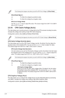
Channel A/B DIMM Control [Enable Both DIMMs] This item allows you to enable or disable the DIMMs on channels A and B. Configuration options: [Enable Both DIMMS] [Disable DIMM0] [Disable DIMM1] [Disable Both DIMMS] Scrambler Setting [Optimized (ASUS)] This item allows you to set the optimized mode to enhance system stability. Configuration options: [Optimized (ASUS] [Default (MRC)] MCH Full Check [Auto] Enable this item to enhance the stability of your system. Disable this item to enhance the DRAM overclocking capability. Configuration options: [Auto] [Enabled] [Disabled] Skew Control The subitems in this menu allows you to enhance the DRAM overclocking capability and stability. Use the or keys to adjust the value. To restore the default setting, type [Auto] using the keyboard and press the key. Transmitter Rising Slope [Auto] Configuration options: [Auto] [1] - [31] Transmitter Falling Slope [Auto] Configuration options: [Auto] [1] - [31] Transmitter Control Time [Auto] Configuration options: [Auto] [1] - [31] Receiver Rising Slope [Auto] Configuration options: [Auto] [1] - [31] Receiver Falling Slope [Auto] Configuration options: [Auto] [1] - [31] Receiver Control Time [Auto] Configuration options: [Auto] [1] - [31] 2.5.14 DIGI+ VRM CPU Load-line Calibration [Auto] Load-line is defined by Intel® specification and affects CPU power voltage. The CPU working voltage decreases proportionally to CPU loading. Higher load-line calibration could get higher voltage and good overclocking performance, but increases the CPU and VRM thermal conditions. Select from levels 1 to 9 to adjust the CPU power voltage from 0% to 115%. Configuration options [Auto] [Level 1] - [Level 9] The actual performance boost may vary depending on your CPU specification. DO NOT remove the thermal module. The thermal conditions should be monitored. ASUS Z97-A 2-25
-
 1
1 -
2
-
3
-
4
-
5
-
6
-
7
-
8
-
9
-
10
-
11
-
12
-
13
-
14
-
15
-
16
-
17
-
18
-
19
-
20
-
21
-
22
-
23
-
24
-
25
-
26
-
27
-
28
-
29
-
30
-
31
-
32
-
33
-
34
-
35
-
36
-
37
-
38
-
39
-
40
-
41
-
42
-
43
-
44
-
45
-
46
-
47
-
48
-
49
-
50
-
51
-
52
-
53
-
54
-
55
-
56
-
57
-
58
-
59
-
60
-
61
-
62
-
63
-
64
-
65
-
66
-
67
-
68
-
69
-
70
-
71
-
 72
72 -
 73
73 -
 74
74 -
 75
75 -
 76
76 -
 77
77 -
 78
78 -
 79
79 -
 80
80 -
 81
81 -
 82
82 -
83
-
84
-
85
-
86
-
87
-
88
-
89
-
90
-
91
-
92
-
93
-
94
-
95
-
96
-
97
-
98
-
99
-
100
-
101
-
102
-
103
-
104
-
105
-
106
-
107
-
108
-
109
-
110
-
111
-
112
-
113
-
114
 |
 |