Asus Z9PE-D16-10G DUAL Z9PE-D16-10G Series Manual - Page 30
thumb C, then move it to the right D, Lift the load lever in the direction of
 |
View all Asus Z9PE-D16-10G DUAL manuals
Add to My Manuals
Save this manual to your list of manuals |
Page 30 highlights
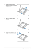
2. Press the left load lever with your thumb (A), then move it to the left (B) until it is A released from the retention tab. To prevent damage to the socket pins, do not remove the PnP cap unless you are installing a CPU. B Load lever 3. Slightly lift the load lever in the direction of the arrow. 4. Press the right load lever with your thumb (C), then move it to the right (D) until it is released from the retention tab. Lift the load lever in the direction of the arrow (E). E C D 2-10 Chapter 2: Hardware information
-
 1
1 -
2
-
3
-
4
-
5
-
6
-
7
-
8
-
9
-
10
-
11
-
12
-
13
-
14
-
15
-
16
-
17
-
18
-
19
-
20
-
21
-
22
-
23
-
24
-
 25
25 -
 26
26 -
 27
27 -
 28
28 -
 29
29 -
 30
30 -
 31
31 -
 32
32 -
 33
33 -
 34
34 -
 35
35 -
36
-
37
-
38
-
39
-
40
-
41
-
42
-
43
-
44
-
45
-
46
-
47
-
48
-
49
-
50
-
51
-
52
-
53
-
54
-
55
-
56
-
57
-
58
-
59
-
60
-
61
-
62
-
63
-
64
-
65
-
66
-
67
-
68
-
69
-
70
-
71
-
72
-
73
-
74
-
75
-
76
-
77
-
78
-
79
-
80
-
81
-
82
-
83
-
84
-
85
-
86
-
87
-
88
-
89
-
90
-
91
-
92
-
93
-
94
-
95
-
96
-
97
-
98
-
99
-
100
-
101
-
102
-
103
-
104
-
105
-
106
-
107
-
108
-
109
-
110
-
111
-
112
-
113
-
114
-
115
-
116
-
117
-
118
-
119
-
120
-
121
-
122
-
123
-
124
-
125
-
126
-
127
-
128
-
129
-
130
-
131
-
132
-
133
-
134
-
135
-
136
-
137
-
138
-
139
-
140
-
141
-
142
-
143
-
144
-
145
-
146
-
147
-
148
-
149
-
150
-
151
-
152
-
153
-
154
-
155
-
156
-
157
-
158
-
159
-
160
-
161
-
162
-
163
-
164
-
165
-
166
-
167
-
168
-
169
-
170
-
171
-
172
-
173
-
174
-
175
-
176
-
177
-
178
-
179
-
180
-
181
-
182
-
183
-
184
-
185
-
186
-
187
-
188
-
189
-
190
-
191
-
192
-
193
-
194
-
195
-
196
-
197
-
198
-
199
-
200
-
201
-
202
 |
 |

2-10
Chapter 2: Hardware information
2.
Press the left load lever with your thumb
(A), then move it to the left (B) until it is
released from the retention tab.
To prevent damage to the socket pins,
do not remove the PnP cap unless
you are installing a CPU.
B
A
E
D
C
4.
Press the right load lever with your
thumb (C), then move it to the right (D)
until it is released from the retention tab.
Lift the load lever in the direction of the
arrow (E).
3.
Slightly lift the load lever in the direction
of the arrow.
Load lever