Asus a7n8x A7N8X User Manual - Page 2
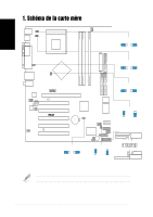
Schéma de la carte mère
 |
View all Asus a7n8x manuals
Add to My Manuals
Save this manual to your list of manuals |
Page 2 highlights
Français 1. Schéma de la carte mère PS/2 T: Mouse B: Keyboard USB3 USB4 COM1 KBPWR1 USBPWR_34 Socket 462 CPU_FAN1 KBPWR1 12 23 +5V (Default) +5VSB DDR DIMM1 (64/72 bit, 184-pin module) DDR DIMM2 (64/72 bit, 184-pin module) DDR DIMM3 (64/72 bit, 184-pin module) ATX Power Connector FLOPPY1 PARALLEL PORT USBPWR_12 Bottom: USB1 USB2 Top: RJ-45 Top:Line In Center:Line Out Below:Mic In CPU_FSB nVidia nForce2 SPP Chipset 0 1 23 4 5 SEC_IDE1 PRI_IDE1 PWR_FAN1 CHA_FAN1 Realtek RTL8201 CD1 FPAUDIO1 AUX1 Audio Codec SPDIF1 Accelerated Graphics Port (AGP Pro) AGP_WARN1 PCI 1 PCI 2 ® A7N8X PCI 3 nForce2 MCP Chipset CR2032 3V Lithium Cell CMOS Power CLRTC1 2Mb BIOS Super I/O USB56 COM2 MODEM1 PWR_LED1 PCI 4 PCI 5 USBPWR_56 ASUS ASIC with Hardware Monitor IR_CON1 PWRTMP1 IDELED1 GAME1 SMB1 CHASSIS1 BUZZ1 CTRL_PANEL1 CLRTC1 12 23 Normal Clear CMOS (Default) USBPWR_56 1 2 +5V (Default) 2 3 +5VSB USBPWR_34 12 23 +5V (Default) +5VSB USBPWR_12 12 23 +5V (Default) +5VSB CPU_FSB 1 2 FSB333/266 (Default) 2 3 FSB200 CTRL_PANEL1 Verrouillage du clavier LED alimentation Connecteur Haut-parleur PLED+ PLEDKeylock Ground +5V Ground Ground Speaker ExtSMI# Ground PWR Ground Reset Ground SMI Lead Bouton de reset Commutateur d'alimentation ATX * Nécessite une alimentation ATX. Les composants optionnels sont en gris sur le layout de la carte mère. 2 Carte mère ASUS A7N8X
-
 1
1 -
 2
2 -
 3
3 -
 4
4 -
 5
5 -
 6
6 -
 7
7 -
 8
8 -
9
-
10
-
11
-
12
-
13
-
14
-
15
-
16
 |
 |
