Audiovox APS687 Installation Manual
Audiovox APS687 - Car Prestige Remote Start Manual
 |
UPC - 044476036705
View all Audiovox APS687 manuals
Add to My Manuals
Save this manual to your list of manuals |
Audiovox APS687 manual content summary:
- Audiovox APS687 | Installation Manual - Page 1
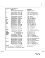
APS-687 Installation Manual The selectable features can be set manually as explained below, or with the RF feature programmer. To set features using the RF programmer, follow the instructions Guide /Hd Wire Not Available valet switch 3 times; turn ignition off then on. Press and hold valet switch - Audiovox APS687 | Installation Manual - Page 2
to change or Fourth Press and release the valet switch or Fifth Press and release the valet switch or Sixth Press and release the valet switch or Seventh Press and release the valet switch or Eighth Press and release the valet switch Press transmitter Lock button to change Press - Audiovox APS687 | Installation Manual - Page 3
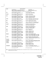
To exit program mode, turn ignition off, or press and release valet switch. RF Programmable Features Bank 3 Is Remote Start Selectable Features: Feature Selection 1 Chirp 2 Chirps 3 Chirps 4 Chirps 1st Defrost Output Pulsed 10 Mins 2nd RF Start Chirp Off On On & Car Finder 3rd Run Time - Audiovox APS687 | Installation Manual - Page 4
Off, On, Off, On Short chirp, then 2 long chirps This Action Accesses Feature Bank 3 Remote Start Selectable Features Press the valet switch one time Press transmitter Lock button to change or Press and release the valet switch Press transmitter Lock button to change or Press and release the - Audiovox APS687 | Installation Manual - Page 5
transmitters, and for overriding the remote start unit when the vehicle is being serviced. Inspect behind the chosen location to insure that adequate clearance is allowed for the body of the switch, and also that the drill will not penetrate any existing factory wiring or fluid lines. Drill a 5/16 - Audiovox APS687 | Installation Manual - Page 6
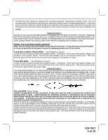
responsibility of the installing technician to test the remote start unit and assure that the vehicle cannot start via RF control in any gear selection other than park or neutral. In both mechanical and electrical neutral start switch configurations, the connection of the Yellow wire will be made - Audiovox APS687 | Installation Manual - Page 7
neutral safety switch as shown in the following diagram. Failure to connect this wire to the ignition switch side of the neutral safety switch can result in personal injury and property damage. SEE NEUTRAL START SAFETY TEST FOR FURTHER DETAILS. BLUE WIRE: Ignition 1 Output Connect this wire to the - Audiovox APS687 | Installation Manual - Page 8
selected to be on or off during the start cycle. (See feature bank 3 selection # 8) Connect this wire to the third ignition circuit in the vehicle and set the selectable feature # 8 of Bank 3 according to the way in which the vehicle's ignition switch operates. Note: Do not remove the fuse holders - Audiovox APS687 | Installation Manual - Page 9
+ 12 Volts is applied to the Brown wire, the Remote Starter will stop operating, even if the signal is received from the transmitter. If the vehicle has a factory installed hood pin switch and that switch provides + 12 Volts to an under hood light, the Brown wire can be connected to the existing pin - Audiovox APS687 | Installation Manual - Page 10
chassis ground source, and connect the second White wire to the vehicle's parking light wire. Switch LIGHT BLUE Wire: Ignition 3 / Shock Disable Output This wire provides a 300mA ground output that becomes active 3 seconds before the Remote Start Unit initializes, and remains grounded while running - Audiovox APS687 | Installation Manual - Page 11
factory service manual for additional information. 3. Connect the Light Blue Wire from the Remote Start Unit to terminal #86 of an external relay. Connect terminal #85 of the relay to a fused + 12 volt battery source. 4. Cut (#1) wire (as shown), and connect the ignition switch side of the cut wire - Audiovox APS687 | Installation Manual - Page 12
: Pulsed Ground Output After Shutdown The Black w/ Red Trace wire will provide a 1 second 300 mA pulsed ground output after the remote start unit shuts down. This output will occur regardless of whether the circuit times out or is manually terminated. Typically this output will be used to re-lock - Audiovox APS687 | Installation Manual - Page 13
, or press and release the trunk/key button two times within 2 seconds to activate the remote starter. WARNING: Connecting the dark blue wire to the high current switched output of the trunk release circuits and some remote start trigger inputs, will damage the control module. Connect the dark blue - Audiovox APS687 | Installation Manual - Page 14
Wire: External Trigger Input The Dark Blue/Black trace wire allows the remote start unit to be activated from an external source. The intent of this wire from the vehicle's horn switch. If the vehicle uses a + 12 VDC horn switch, then connect the black w/ white trace wire to terminal 86 of the - Audiovox APS687 | Installation Manual - Page 15
3. Connect the Yellow wire to a +12 volt ignition 1 source. This wire will have +12 volts with the ignition in the on and start position and have 0 volts with the ignition in the off position. 4. Connect the Green wire to the (Green) or (Orange/Green) tach input of the Audiovox remote start unit. 15 - Audiovox APS687 | Installation Manual - Page 16
the unit fails this test, recheck your pin switch connection to the Gray/Black wire of the Audiovox Remote Start Unit. WARNING!! DO NOT RELEASE THIS VEHICLE TO THE CONSUMER UNTIL YOU CONFIRM THE OPERATION OF THE HOOD PIN SAFETY SHUT DOWN FEATURE. MANUAL SHUT DOWN / ENABLE CIRCUIT: The intent of the - Audiovox APS687 | Installation Manual - Page 17
the equivalent reference wire in the vehicle you are installing the Audiovox Remote Start Unit in. 2. Connect the Cathode, (Striped) end, of a 4000 series diode to this reference wire. 3. Connect the Anode, (Non Striped) end, of the diode to one side of the Remote Start enable switch. 4. Connect the - Audiovox APS687 | Installation Manual - Page 18
this is the case, it must be installed as shown in the diagram above. The anode (Non Striped) side must be connected to the Gray/Black wire of the Remote Start Unit. The cathode (Striped) side must be connected to the hood pin switch. If the hood pin switch is also used for an alarm trigger input - Audiovox APS687 | Installation Manual - Page 19
connected to the hood pin switch. If the hood pin switch is also used for an alarm trigger input, be certain to use the dual diode assembly packaged with the Audiovox Remote Start Unit as shown in this installation guide. AFTER THE CONNECTION OF THE NEUTRAL START SAFETY WIRE AS INDICATED IN ANY OF - Audiovox APS687 | Installation Manual - Page 20
© 2006 Audiovox Electronics Corp., Hauppauge, NY 11788 20 128-7827 128-7827 20 of 20
-
 1
1 -
 2
2 -
 3
3 -
 4
4 -
 5
5 -
 6
6 -
 7
7 -
8
-
9
-
10
-
11
-
12
-
13
-
14
-
15
-
16
-
17
-
18
-
19
-
20
 |
 |

128-7827
1 of 20
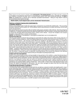
The selectable features can be set manually as explained below, or with the RF feature programmer.
To set features using the RF programmer, follow the instructions packaged with the programmer.
Factory default settings are indicated by bold text.
Note :
The method of manual override can either be selected to operate from the valet switch or operate as custom code.
Be certain to place a check mark indicating the method used in the box located on the last page of the owner's manual.
NOTE: Keyless Entry Models with no horn output will Flash the Parking Lights instead of chirp where chirp is indicated.
Also, No data will be indicated if a feature is not available for a particular model.
The unit will enter the feature but no selection will be available.
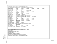
RF Programmable Feature Bank 1 Is For Transmitter Programming See Transmitter Programming Guide.
RF Programmable Features Bank 2 Is Alarm Selectable Features:
Feature Selection
1 Chirp
2 Chirps
3 Chirps
4 Chirps
5 Chirps
6 Chirps
1st DoorL/UL
1 Sec.
3.5 Sec.
1 Sec L, Dbl. U/L
Dbl L, 1 Sec UL
Dbl L, Dbl UL
1 S l/350mS ul
2nd
Accy Lock
Auto Lock On
Auto Lock Off
3rd
Accy
. UL
Auto UL Dr.
Auto UL All
Auto UL Off
`
4th Headlights
Not Available
5th Passive Locks
Not Available
6th Pass/Act
Arm
Not Available
7th Siren/Horn
Not Available
8th Horn Chirp
10mS
16mS
30mS
40mS
50mS
9th O/R Method
Not Available
10th 2 S
tep U/L
On
Off
1
1th Chp Del
Tx
On
Off
12th Vlot Sense/Hd Wire
Not Available
13th Trigger Circuits
Not Available
14th L/UL Poll
Not Available
15th
Aux Ch 5 Sel
Pulse
Push & Hold
10 Sec
20 Sec
Latch On/Off
Hold 3/S For O/P
16th
Aux Ch 6 Sel
Pulse
Push & Hold
10 Sec
20 Sec
Latch On/Off
Hold 3/S For O/P
17th
Aux Ch 7 Sel
Pulse
Push & Hold
10 Sec
20 Sec
Latch On/Off
Hold 3/S For O/P
18th Trigger Delay
Not Available
When using the RF programmer, enter the program mode as follows:
Turn the ignition on.
Press and release valet switch 3 times;
turn ignition off then on.
Press and hold valet switch for 5 seconds.
Siren and or lights chirp/flash 2 times indicating access to RF feature program mode.
Model APS-687
Installation Manual