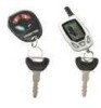
Audiovox APS996A Instruction Manual
Audiovox APS996A - Prestige Remote Security System Manual
 |
UPC - 044476014970
View all Audiovox APS996A manuals
Add to My Manuals
Save this manual to your list of manuals |
Audiovox APS996A manual content summary:
- Audiovox APS996A | Instruction Manual - Page 1
Model APS 996a Installation Manual SELECTABLE FEATURES Note : The method of manual override can either be selected to operate from the valet switch or operate as custom code. Be certain to place a check mark indicating the method used in the box located on the last page of the owner's manual program - Audiovox APS996A | Instruction Manual - Page 2
THIS PAGE INTENTIONALLY LEFT BLANK 128-6773 2 of 28 - Audiovox APS996A | Instruction Manual - Page 3
inactive 1 chirp = chirp delete from transmitter active Exit program mode Exit program mode Note : Once you enter the feature programming mode, do not allow more than 15 seconds to pass between steps or the programming will be terminated. The APS-996 Remote Start/Alarm System is designed to be used - Audiovox APS996A | Instruction Manual - Page 4
in the kit will serve as a visual indicator of the alarm's status and provide a visual deterrent to a potential thief. The LED also provides important feed back information during the transmitter and feature program modes. The LED should be installed in the dash in an area highly visible so that it - Audiovox APS996A | Instruction Manual - Page 5
the control module to allow routing Wire the relay as per the diagram found later in this manual. The APS-996 is to be used in vehicles with AUTOMATIC TRANSMISSIONS only! Although this combination Alarm/Remote Start unit is a sophisticated system with many advanced features, IT MUST NOT be installed - Audiovox APS996A | Instruction Manual - Page 6
wire is required for all mechanical switch configurations. Failure to make this connection properly can result in personal injury and property damage. In all installations it is the responsibility of the installing technician to test the remote following diagram. Failure to connect this wire to the - Audiovox APS996A | Instruction Manual - Page 7
Parking Light Flasher Output This wire is the normally open contact of the on board parking light flasher relay. Connect this wire to the vehicle parking light feed wire. See diagram below for details on wiring positive switched parking light circuits. Parking Light Wiring Detail 6 128-6773 7 of 28 - Audiovox APS996A | Instruction Manual - Page 8
previously installed. NOTE: This wire will be shunted when remote control channel 3 is accessed, (trunk release). This wire will remain shunted all the while there is ground present and for 5 seconds after the ground is removed. This allows the operator to open the trunk via the remote transmitter - Audiovox APS996A | Instruction Manual - Page 9
Violet w/ Yellow trace, however in later model Cadillacs, they are run through an orange sleeve, and are either both Black, both Yellow, or both White wires. Consult the factory service manual for additional information. 3. Connect the Light Blue Wire from the Remote Start Unit to terminal #86 of an - Audiovox APS996A | Instruction Manual - Page 10
When Armed The Grey w/ Black Trace wire provides an instant shutdown for the Remote Start Control Module whenever it is grounded also trigger for the alarm when armed. Connect the Grey w/ Black trace wire to the hood pin switch previously installed. This wire must be routed through a grommet in - Audiovox APS996A | Instruction Manual - Page 11
Inhibit Input Plus Trigger When Armed The Brown w/ Black Trace wire provides an instant shutdown for the Remote Start Control module whenever it gets + 12 volts also triggers the alarm when armed. If the Brake lights switch in the vehicle switches + 12 volts to the brake light circuit, connect - Audiovox APS996A | Instruction Manual - Page 12
, the siren will emit three chirps. When the zone clears, the siren will emit 1 chirp to confirm full arming. See below for wiring detail. Note for vehicles with interior delay lighting see programming under title "Completing The Installation". Negative Door Switch Wiring Detail 11 128-6773 12 of 28 - Audiovox APS996A | Instruction Manual - Page 13
See below for relay wiring detail. Channel 3 Relay Wiring Detail Green w/ Black Trace Wire: 300mA Latched Channel 4 Output The Green w/ Black Trace wire supplies a 300 mA switched output whenever channel four of the receiver is accessed. Pressing the pre-programmed transmitter button(s) will access - Audiovox APS996A | Instruction Manual - Page 14
wire will provide a 1 second 300 mA pulsed ground output 1.5 second before the remote start unit activates as well as when the transmitter is used to disarm the system. Typical use for this output would be to disarm a factory theft deterrent system to prevent false triggering of the factory alarm - Audiovox APS996A | Instruction Manual - Page 15
shell of the control module. Refer to the remote programming, feature programming and function programming shown later in this installation guide for operation of the valet/program switch. For override information, refer to the owners manual. 4 Pin Antenna/Receiver Connector: (White Connector - Audiovox APS996A | Instruction Manual - Page 16
factory door lock switch to the factory door lock relay. See Below For Wiring Detail. 3 Wire Positive Switched Door Lock/Unlock Wiring Detail 3 Wire Ground Switched 2 Step Door Locks: In this application, the red wire provides a ground pulse during arming, or the pulsed ground lock output. Connect - Audiovox APS996A | Instruction Manual - Page 17
ground to the door lock/unlock motors, connect he remaining terminal, 87, to chassis ground. The Red/Black wire provides a pulse ground output when the unlock button of the transmitter is pressed a second time after disarming. Because the vehicle you are working on requires a positive pulse from the - Audiovox APS996A | Instruction Manual - Page 18
and or the Audiovox fax back service for information on your particular vehicle for properly connecting to these types of circuits. ALARM SELECTABLE FEATURES NOTE: The Alarm Selectable Features and Remote Start Selectable Features programming steps following are based on transmitter button 1 being - Audiovox APS996A | Instruction Manual - Page 19
certain to connect the tach input wire. To Program The Remote Start Selectable Features: 1. Turn the ignition key to the On position. 2. Press and release the valet/program switch three times. 3. Immediately turn the ignition key Off then press transmitter start button for 1 second. 4. Immediately - Audiovox APS996A | Instruction Manual - Page 20
the transmitter /program pushbutton wire to a +12 volt ignition 1 source. This wire will have +12 volts with the ignition in the on and start position and have 0 volts with the ignition in the off position. 4. Connect the Green wire to the (Green) or (Orange/Green) tach input of the Audiovox remote - Audiovox APS996A | Instruction Manual - Page 21
start the vehicle using the RF transmitter. 2. Reach inside the car and pull the hood release. 3. Raise the hood and confirm that the remote start unit shuts down. If the unit fails this test, recheck your pin switch connection to the Gray/Black wire of the Audiovox Remote Start Unit. DO NOT RELEASE - Audiovox APS996A | Instruction Manual - Page 22
the brake pedal depressed, activate the RF transmitter in an attempt to start the vehicle. The car should not start. 8. Repeat the above test wire in the vehicle you are installing the Audiovox Remote Start Unit in. 2. Connect the Cathode, (Striped) end of a 4000 series diode to this reference wire - Audiovox APS996A | Instruction Manual - Page 23
ECM reference wire, there are gear. AUDIOVOX ADVISES installation manual. Additional information concerning Key In Sensor methods 1 & 2 are listed below and should be reviewed before considering either alternative. Method 1 will allow the safety required for the remote module will not alert the owner - Audiovox APS996A | Instruction Manual - Page 24
. If the hood pin switch is also used for an alarm trigger input, be certain to use the dual diode assembly packaged with the Audiovox Remote Start Unit as shown in this installation guide. (Page 9) AFTER THE CONNECTION OF THE NEUTRAL START SAFETY WIRE AS INDICATED IN ANY OF THE PREVIOUS ALTERNATE - Audiovox APS996A | Instruction Manual - Page 25
the program switch. 2. Mount the control module up and behind the dash securing it in place with cable ties or screws. Be certain that the chosen mounting location will not inhibit any of the controls of the vehicle. 3. Securely harness and tie all wiring up and away from all hot and moving parts - Audiovox APS996A | Instruction Manual - Page 26
25 128-6773 26 of 28 128-6773 - Audiovox APS996A | Instruction Manual - Page 27
THIS PAGE INTENTIONALLY LEFT BLANK 128-6773 27 of 28 - Audiovox APS996A | Instruction Manual - Page 28
For Custom er Service Visit O ur W ebsite At 999.audiovox.com Product Inform ation, Photos, FA Q 's O w ner 's M a nuals © 2003 Audiovox Electronics Corp., Hauppauge, NY 11788 128-6773 28 of 28 128-6773
-
 1
1 -
 2
2 -
 3
3 -
 4
4 -
 5
5 -
 6
6 -
 7
7 -
8
-
9
-
10
-
11
-
12
-
13
-
14
-
15
-
16
-
17
-
18
-
19
-
20
-
21
-
22
-
23
-
24
-
25
-
26
-
27
-
28
 |
 |

128-6773
1 of 28
Model APS 996a
Installation Manual
RY
SELECT
ABLE FEA
TURES
Note :
The method of manual override can either be selected to operate from the valet switch or operate as custom code.
Be
certain to place a check mark indicating the method used in the box located on the last page of the owner's manual.
RF Programmable Features :
Feature Selection
1 Chirp
2 Chirps
3 Chirps
4 Chirps
Default
1st DoorL/UL
1 Sec.
3.5 Sec.
1 Sec L, Dbl. U/L
1 Sec.
2nd Accy Lock
Auto Lock On
Auto Lock Off
Auto Lock Off
3rd Accy
. UL
Auto UL Dr.
Auto UL All
Auto UL Off
Auto UL Off
4th Headlights
On Arm
On Disarm
On Both
Off
Both
5th Passive Locks
Passive
Active
Active
6th Passive/Active Arm
Passive Arm
Active Arm
Active Arm
7th Black/Blue (Aux O/P)
Single Pulse
As Feature #1
Single
8th Siren/Horn
Siren/Horn
Siren Only
Horn Only
Siren/Horn
9th Horn Chirp
10mS
16mS
30mS
16mS
10th Override Method
Custom Code
Valet
Valet
1
1th T
wo Step Unlock
On
Off
Off
12th Chirp Delete From Tx
On
Off
Off
To program these selectable features;
Action
System Response
Turn ignition on
No response
Press and release the valet switch 3 times
1 Chirp - LED 1 flash
Within 3 seconds, turn ignition Off
Short chirp, then long chirp
First
Then turn the ignition back On
1 chirp = 1 second door locks
Press transmitter Lock button to change
2 chirps = 3.5 second door locks
Press transmitter Lock button to change
3 chirps = 1 sec. lock, dbl 1 sec. unlock
or
Second
Press and release the valet switch
2 chirps = auto locks off
Press transmitter Lock button to change
1 chirp = auto locks on
or
Third
Press and release the valet switch
3 chirps = auto unlock off
Press transmitter Lock button to change
1 chirp = auto unlock drivers door only
Press transmitter Lock button to change
2 chirps = auto unlock all doors
or
Fourth
Press and release the valet switch
3 chirps = headlight output when arming and disarming
Press transmitter Lock button to change
4 chirps = headlight output off
Press transmitter Lock button to change
1 chirp = headlight output when arming
Press transmitter Lock button to change
2 chirps = headlight output when disarming
or
Fifth
Press and release the valet switch
2 chirps = active locks
Press transmitter Lock button to change
1 chirp = passive locks
or
Sixth
Press and release the valet switch
2 chirps = active arming
Press transmitter Lock button to change
1 chirp = passive arming
or
Seventh
Press and release the valet switch
2 chirps = as feature #1
Press transmitter Lock button to change
1 chirp = single pulse
or