Audiovox APS996A Instruction Manual - Page 10
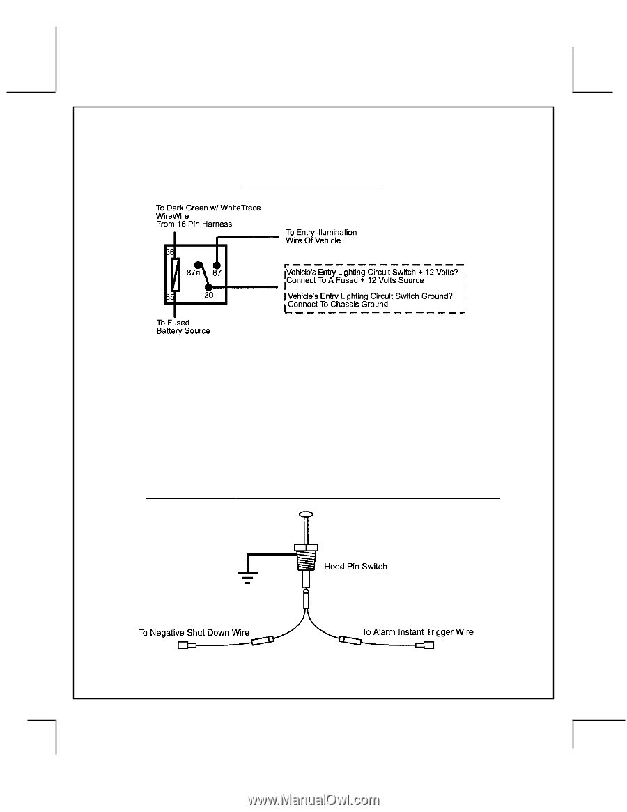
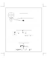
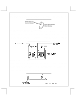
Entry Illumination Detail, Grey w/ Black T, race Negative Inhibit Safety Shut Down Detail - alarm
 |
UPC - 044476014970
View all Audiovox APS996A manuals
Add to My Manuals
Save this manual to your list of manuals |
Page 10 highlights
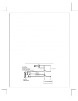
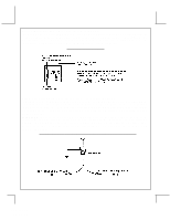
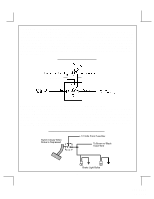
Green w/ White trace Wire: Entry Illumination Ground Output This wire provides a 30 second ground output (300 mA Max.) whenever the remote is used to disarm the alarm or to unlock the doors and provides a continuous pulsed output whenever the alarm is triggered. This wire should be connected to an external relay and wired to the vehicles interior entry lighting whenever the optional Interior Illumination circuit is desired. See below for relay wiring details. Entry Illumination Detail Grey w/ Black Trace Wire: Negative Inhibit Input Plus Trigger When Armed The Grey w/ Black Trace wire provides an instant shutdown for the Remote Start Control Module whenever it is grounded also trigger for the alarm when armed. Connect the Grey w/ Black trace wire to the hood pin switch previously installed. This wire must be routed through a grommet in the firewall and connected to the hood pin switch. If the pin switch is to be used with an alarm system, connect this wire using the diode assembly provided. IMPORTANT! This connection is a safety wire and must be connected as shown and tested as specified. Failure to do so may result in personal injury or property damage. See detail of wiring in the following diagram. This wire may also be used if the vehicle brake light circuit switches ground to the brake lights. An isolation diode must be used for ground switched brake light circuits and must be connected to the output of the brake switch. Grey w/ Black Trace Negative Inhibit Safety Shut Down Detail 9 128-6773 10 of 28
-
 1
1 -
2
-
3
-
4
-
 5
5 -
 6
6 -
 7
7 -
 8
8 -
 9
9 -
 10
10 -
 11
11 -
 12
12 -
 13
13 -
 14
14 -
 15
15 -
16
-
17
-
18
-
19
-
20
-
21
-
22
-
23
-
24
-
25
-
26
-
27
-
28
 |
 |