Audiovox APS997A Installation Manual
Audiovox APS997A - Car - Remote Start Manual
 |
UPC - 044476043406
View all Audiovox APS997A manuals
Add to My Manuals
Save this manual to your list of manuals |
Audiovox APS997A manual content summary:
- Audiovox APS997A | Installation Manual - Page 1
can either be selected to operate from the valet switch or operate as custom code. Be certain to place a check mark indicating the method used in the box located on the last page of the owner's manual. NOTE: Keyless Entry Models with no horn output will Flash the Parking Lights instead of chirp - Audiovox APS997A | Installation Manual - Page 2
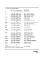
To program these selectable features; Action System Response Turn ignition on No response Press and release the valet switch 3 times 1 Chirp - LED 1 flash Within 3 seconds, turn ignition Off Then On Short chirp, then long chirp This Action Accesses Feature Bank 2 Alarm Selectable Features - Audiovox APS997A | Installation Manual - Page 3
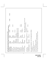
3 of 28 To exit program mode, turn ignition off, or press and release valet switch. RF Programmable Features Bank 3 Is Remote Start Selectable Features: Feature Selection 1 Chirp 2 Chirps 3 Chirps 4 Chirps 5 Chirps 1st Defrost Output Pulsed 10 Mins 2nd RF Start Chirp Off On 3rd Run - Audiovox APS997A | Installation Manual - Page 4
Feature Bank 3 Remote Start Selectable Features First Press the valet switch one time Press transmitter Lock button to change or Second Press and release the valet switch Press transmitter /Blue as alarm feature #1 Exit Programming Mode Note : Once you enter the feature programming mode, do - Audiovox APS997A | Installation Manual - Page 5
to the input wire activating the alarm. In addition, the hood switch is required for the safety shut down of the remote start unit. If the vehicle is being worked on, this hood switch prevents the remote start activation even if the RF command to start is issued. This switch must be installed in all - Audiovox APS997A | Installation Manual - Page 6
sheet metal screw. Wire the relay as per the diagram found later in this manual. This unit is to be used in vehicles with AUTOMATIC TRANSMISSIONS only! Although this combination Alarm/Remote Start unit is a sophisticated system with many advanced features, IT MUST NOT be installed into a vehicle - Audiovox APS997A | Installation Manual - Page 7
register voltage in all positions of the ignition switch. Connect the Red wire to the vehicle's battery wire. This wire provides power for the start relay and the accessory relay. I M P O R TA N T ! IT IS THE RESPONSIBILITY OF THE INSTALLING TECHNICIAN TO DETERMINE THE LOAD FACTOR OF THE VEHICLES - Audiovox APS997A | Installation Manual - Page 8
diagram. Failure to connect this wire to the ignition switch side of the of the neutral safety switch can result in personal injury and property damage. SEE NEUTRAL START SAFETY TEST FOR FURTHER DETAILS. YELLOW START WIRE DETAIL BLUE Wire: Ignition 1 Output Connect this wire to the ignition 1 wire - Audiovox APS997A | Installation Manual - Page 9
turned to the "OFF" and "ACCESSORY" positions. NOTE: See programming information (Bank 3 Selection #2) concerning this wire to allow output during the "START" mode. VIOLET Wire: Accessory Output Connect this wire to the Accessory wire from the ignition switch. This wire will show + 12 volts when the - Audiovox APS997A | Installation Manual - Page 10
relay. Connect this wire to the vehicle parking light feed wire. See diagram below for details on wiring positive switched parking light circuits. Parking Light Wiring Detail White w/ Black Trace Wire: (+) Siren Output This is the positive siren feed wire. Route this wire through a grommet in - Audiovox APS997A | Installation Manual - Page 11
to open the trunk via the remote transmitter without having to first disarm the alarm system. See below for wiring detail. Hood Pin Switch Detail Light Blue Wire: Ground Output While Running Under Remote Start Control This wire provides a 300mA ground output that becomes active 3 seconds before the - Audiovox APS997A | Installation Manual - Page 12
. For GM PASS LOCK System you will require the Audiovox AS-PASS II Module. General Motors VATS By-Pass Diagram Green w/ White trace Wire: Entry Illumination Ground Output This wire provides a 30 second ground output (300 mA Max.) whenever the remote is used to disarm the alarm or to unlock the doors - Audiovox APS997A | Installation Manual - Page 13
When Armed The Grey w/ Black Trace wire provides an instant shutdown for the Remote Start Control Module whenever it is grounded also trigger for the alarm when armed. Connect the Grey w/ Black trace wire to the hood pin switch previously installed. This wire must be routed through a grommet in - Audiovox APS997A | Installation Manual - Page 14
whenever it gets + 12 volts also triggers the alarm when armed. If the Brake lights switch in the vehicle switches + 12 volts to the brake light circuit, connect the Brown w/ Black trace wire to the output side of the brake switch. This will allow the Remote Start to shut down if an attempt is made - Audiovox APS997A | Installation Manual - Page 15
title "Completing The Installation". Negative Door Switch Wiring Detail Dark Blue Wire: Delayed 300mA Pulsed Channel 3 Output The Dark Blue wire supplies a 300mA ground pulsed output whenever channel three of the receiver is accessed. Pressing the pre-programmed transmitter button for three seconds - Audiovox APS997A | Installation Manual - Page 16
from a "POSSE/CAR-LINK" paging system or similar device. When this wire receives a ground pulse, the unit will start the vehicle. Connect this wire to a ground pulsed output from the controlling circuit. Black w/ White Trace Wire : 300 mA Horn Output The black w/ white trace wire is provided to - Audiovox APS997A | Installation Manual - Page 17
factory alarm when the remote start unit engages or when the system is used to unlock the doors. NOTE: This output can be selected to operate like the door lock output as set in alarm feature setting #1 by selecting feature #7 on. Black w/ Light Green Trace Wire: Pulsed Ground Output After Start The - Audiovox APS997A | Installation Manual - Page 18
shell of the control module. Refer to the remote programming, feature programming and function programming shown later in this installation guide for operation of the valet/program switch. For override information, refer to the owners manual. 4 Pin Antenna/Receiver Connector: Plug the previously - Audiovox APS997A | Installation Manual - Page 19
, or pulsed 12 volt lock output. Connect the Green wire to the low current 12 volt signal wire from the factory door lock switch to the factory door lock relay. See Below For Wiring Detail. 3 Wire Positive Switched Door Lock/Unlock Wiring Detail 3 Wire Ground Switched 2 Step Door Locks: In this - Audiovox APS997A | Installation Manual - Page 20
pulse ground output when the unlock button of the transmitter is pressed a second time after disarming. Connect the Red/Black wire to the wire that provides a low current ground signal from the factory door unlock switch to the factory door unlock control relay. 3 Wire Positive Switched 2 Step Door - Audiovox APS997A | Installation Manual - Page 21
to the AUDIOVOX Door Lock Wiring Supplement and or the Audiovox fax back service for information on your particular vehicle for properly connecting to these types of circuits. START PROGRAM: The Remote Start unit has the ability to start the vehicle automatically at timed intervals. This feature is - Audiovox APS997A | Installation Manual - Page 22
TEMPERATURE START: When Temperature Start, Bank 3 feature #13 is selected on, the temperature start mode can be activated from the transmitter. See owners manual for turning this feature on from the transmitter. Once activated, the unit will start 1 time if the vehicle temperature reaches "0* " and - Audiovox APS997A | Installation Manual - Page 23
the vehicle using the RF transmitter. 2. Reach inside the car and pull the hood release. 3. Raise the hood and confirm that the remote start unit shuts down. If the unit fails this test, recheck your pin switch connection to the Gray/Black wire of the Audiovox Remote Start Unit. DO NOT RELEASE THIS - Audiovox APS997A | Installation Manual - Page 24
MANUAL SHUT DOWN / ENABLE FEATURE. NEUTRAL START SAFETY TEST: The intent of the neutral start switch is to prevent the vehicle from starting while the gear selector is in any position other than Park, or Neutral. When installing a Remote Start Device, it is imperative that the Yellow Starter wire - Audiovox APS997A | Installation Manual - Page 25
side of the enable switch to the Black/White enable input wire of the Remote Start unit. The reference diagram below shows a typical GM B Body ECM reference wire and how it is to be connected to the Remote Start Unit. CAUTION! REMEMBER TO RECONNECT THE BROWN/BLACK WIRE TEMPORARILY DISCONNECTED IN - Audiovox APS997A | Installation Manual - Page 26
/Black wire of the Remote Start Unit. The cathode (Striped) side must be connected to the hood pin switch. If the hood pin switch is also used for an alarm trigger input, be certain to use the dual diode assembly packaged with the Audiovox Remote Start Unit as shown in this installation guide. (Page - Audiovox APS997A | Installation Manual - Page 27
, horn, etc.... to insure proper operation. 6. Replace all panels that were removed during installation, and retest the system. 7. Explain all activated features and safety systems associated with Remote Start Unit installed to the customer. 8. Place the Valet Switch Tag and or the Remote Start - Audiovox APS997A | Installation Manual - Page 28
© 2007 Audiovox Electronics Corp., Hauppauge, NY 11788 28 For Customer Service Visit Our Website At WWW.audiovox.com Product Information, Photos, FAQ's Owner's Manuals 128-8129A 128-8129A 28 of 28
-
 1
1 -
 2
2 -
 3
3 -
 4
4 -
 5
5 -
 6
6 -
 7
7 -
8
-
9
-
10
-
11
-
12
-
13
-
14
-
15
-
16
-
17
-
18
-
19
-
20
-
21
-
22
-
23
-
24
-
25
-
26
-
27
-
28
 |
 |

128-8129A
1 of 28
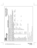
Model APS-997a
Installation Manual
SELECT
ABLE FEA
TURES
The selectable features can be set manually as explained below, or with the RF feature programmer.
To set features using the RF programmer, follow the instructions packaged with the programmer.
Factory default settings are indicated by bold text.
Note :
The method of manual override can either be selected to operate from the valet switch or operate as custom code.
Be certain to place a check mark indicating the method used in the box located on the last page of the owner's manual.
NOTE: Keyless Entry Models with no horn output will Flash the Parking Lights instead of chirp where chirp is indicated.
Also, No data will be indicated if a feature is not available for a particular model.
The unit will enter the feature but no selection will be available.
RF Programmable Feature Bank 1 Is For Transmitter Programming See Transmitter Programming Guide.
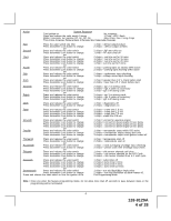
RF Programmable Features Bank 2 Is Alarm Selectable Features:
Feature Selection
1 Chirp
2 Chirps
3 Chirps
4 Chirps
5 Chirps
6 Chirps
1st DoorL/UL
1 Sec.
3.5 Sec.
1 Sec L, Dbl. U/L
Dbl L, 1 Sec UL
Dbl L, Dbl UL
1 S l/350mS ul
2nd
Accy Lock
Auto Lock On
Auto Lock Off
3rd
Accy
. UL
Auto UL Dr.
Auto UL All
Auto UL Off
4th Headlights
On Arm
On Disarm
On Both
Off
5th Passive Locks
Passive
Active
6th Pass/Act
Arm
Passive Arm
Active Arm
7th Siren/Horn
Siren/Horn
Siren Only
Horn Only
8th Horn Chirp
10mS
16mS
30mS
40mS
50mS
9th O/R Method
Custom Code
Valet
10th 2 S
tep U/L
On
Off
1
1th Chp Del
Tx
On
Off
12th V
olt
s/HdW
ire
Not Available
13th Trigger Circuits
Not Available
14th L/UL Poll
Not Available
When using the RF programmer, enter the program mode as follows:
Turn the ignition on
Press and release valet switch 3 times
turn ignition off then on
Press and hold valet switch for 5 seconds
Siren chirps 2 times indicating access to RF feature program mode.
From APS997 with 07SP transmitters 5/07
Rev A: 136-4002 Updated F/W to add DBI Tach, Module Rev 6. 6-30-08