Audiovox APS997A Installation Manual - Page 7
Do not remove the fuse holders from this wire harness. - accessories
 |
UPC - 044476043406
View all Audiovox APS997A manuals
Add to My Manuals
Save this manual to your list of manuals |
Page 7 highlights
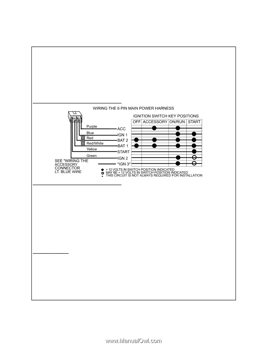
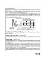
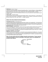
injury and property damage. IMPORTANT! It is the responsibility of the installing technician to determine the load factor of the vehicles electrical circuits when the vehicle is running, and to adequately fuse the three power wires based on that load. If the vehicle, running under load with the air conditioner, heater blower motor, and accessories exceed 24 Amps continuous, we recommend that two fuses be used in combination on each power wire as shown below. For additional information see Tech Update issued 9/30/96. DO NOT PLUG THE SIX PIN MAIN POWER HARNESS OR THE MULTI PIN INPUT / OUTPUT HARNESS INTO THE CONTROL MODULE UNTIL ALL CONNECTIONS TO THE VEHICLE HAVE BEEN MADE. AFTER SELECTING YOUR TARGET WIRES AS DEFINED BELOW, DISCONNECT THE NEGATIVE BATTERY CABLE FROM THE VEHICLE BATTERY PRIOR TO MAKING ANY CONNECTIONS. WIRING THE 6 PIN MAIN POWER HARNESS: WIRING THE 6 PIN MAIN POWER HARNESS: Note: Do not remove the fuse holders from this wire harness. Fuses must be used and located as close as possible to the power source for adequate protection of the vehicle. Fused RED w/ WHITE TRACE WIRE: + 12 volt Battery 1 Source Locate the vehicle battery wire(s) at the ignition switch. Verification: These wires will register voltage in all positions of the ignition switch. Connect the Red w/White wire to the vehicle's battery wire. This wire provides power for the control circuit as well as the ignition 1 and ignition 2 relays. Fused RED WIRE: + 12 Volt Battery 2 Source Locate the vehicle battery wire(s) at the ignition switch. Verification: These wires will register voltage in all positions of the ignition switch. Connect the Red wire to the vehicle's battery wire. This wire provides power for the start relay and the accessory relay. I M P O R TA N T ! IT IS THE RESPONSIBILITY OF THE INSTALLING TECHNICIAN TO DETERMINE THE LOAD FACTOR OF THE VEHICLES ELECTRICAL CIRCUITS WHEN THE VEHICLE IS RUNNING AND TO ADEQUATELY FUSE THE TWO POWER WIRES BASED ON THAT LOAD. IF THE VEHICLE, RUNNING UNDER LOAD WITH THE AIR CONDITIONER, HEATER BLOWER MOTOR, AND ACCESSORIES EXCEEDS 24 AMPS CONTINUOUS, WE RECOMMEND THAT TWO FUSES BE USED IN COMBINATION ON EACH POWER WIRE AS SHOWN BELOW. FOR ADDITIONAL INFORMATION SEE TECH UPDATE ISSUED 9/30/96.IMPORTANT! It is the responsibility of the installing technician to determine the load factor of the vehicles electrical circuits when the vehicle is running, and to adequately fuse the two power wires based on that load. If the 7 128-8129A 7 of 28
-
 1
1 -
 2
2 -
 3
3 -
 4
4 -
 5
5 -
 6
6 -
 7
7 -
 8
8 -
 9
9 -
 10
10 -
 11
11 -
 12
12 -
13
-
14
-
15
-
16
-
17
-
18
-
19
-
20
-
21
-
22
-
23
-
24
-
25
-
26
-
27
-
28
 |
 |