Audiovox FMM100A Installation Instructions
Audiovox FMM100A Manual
 |
View all Audiovox FMM100A manuals
Add to My Manuals
Save this manual to your list of manuals |
Audiovox FMM100A manual content summary:
- Audiovox FMM100A | Installation Instructions - Page 1
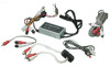
. FM S TE R E O MODULATOR 89.1/88.7 MHz 132-5672 TO RADIO ANT. 18" 36" 7.5" S W1 R E D R C A TO R IG HT WHITE R C A TO LE FT 125V 2A FUS E DC 12V -+- + ANT. IN CH. 3 CH. 4 RF OUT VIDE O AUDIO 15' R C A PATC H C OR D R E QUIR E D FOR S TE R E O C ONNE C TION Y-ADAPTE R R E QUIR E D FOR
-
 1
1
 |
 |

FM Modulator /
Isolation Transformer
Connections
and
Installation
Instructions
NOTE
1. The Vehicle antenna is cut off from the radio when
the power is supplied to the FM modulator via SW1.
Power to the modulator must be switched off in
order to receive normal AM/FM reception.
2. The FM modulator is designed to accept “Line Level”
signals only. These “signals” require amplification to
drive headphones or speakers. (Inputting “Higher”
level audio signals (headphone, external speaker etc)
will override the radio and cause unwanted noise.
Reducing higher level inputs can be achieved through
the use of special “attenuators” or line level reducers.)
3. SW2 is used to select the modulator frequency. The
radio must be turned to the same frequency that was
selected by Switch SW2.
FUSE
125V 2A
DC 12V
-
+
-
+
RF
OUT
ANT.
IN
CH. 3
CH. 4
VIDEO
AUDIO
RCA PATCH CORD REQUIRED FOR STEREO CONNECTION
Y-ADAPTER REQUIRED FOR MONO CONNECTION (6”)
RED RCA TO RIGHT
WHITE RCA TO LEFT
GROUND
+ 12 ACC POWER
DWN
UP
BAND
1
2
3
4
5
6
TONE
OFF/VOL
XXXX/XXXXXX
AS /F S
T /F
▲
▲
TO RADIO
ANTENNA IN
TO VEHICLE
ANTENNA OUT
36”
36”
7.5”
15’
18”
18”
SW1
36”
128-6818
FM STEREO MODULATOR
89.1/88.7
MHz
132-5672
TO RADIO ANT.
TO CAR ANT.
®
ELEC TRO NIC S C O RP.
ELEC TRO NIC S C O RP.
SW2
Date : 22/4/03
PRINTING : ALL IN BLACK WORDINGS, WHITE BASE
With individual Isolation Transformer