Audiovox FMM100A Installation Instructions - Page 1
Audiovox FMM100A Manual
 |
View all Audiovox FMM100A manuals
Add to My Manuals
Save this manual to your list of manuals |
Page 1 highlights
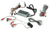
® E LE C TR O N IC S C O R P. F M Modulator / Is olation Trans former C onnec tions and Ins tallation Ins truc tions + 12 AC C POWE R GROUND 36" 36" NOTE 1. The Vehicle antenna is cut off from the radio when the power is s upplied to the FM modulator via S W1. Power to the modulator mus t be s witched off in order to receive normal AM/FM reception. 2. The FM modulator is des igned to accept "Line Level" s ignals only. These "s ignals" require amplification to drive headphones or s peakers . (Inputting "Higher" level audio s ignals (headphone, external s peaker etc) will override the radio and caus e unwanted nois e. R educing higher level inputs can be achieved through the us e of special "attenuators" or line level reducers .) 3. S W2 is used to s elect the modulator frequency. The radio mus t be turned to the s ame frequency that was s elected by S witch S W2. S W2 TO VE HIC LE 18" ANTE NNA OUT TO CAR ANT. FM S TE R E O MODULATOR 89.1/88.7 MHz 132-5672 TO RADIO ANT. 18" 36" 7.5" S W1 R E D R C A TO R IG HT WHITE R C A TO LE FT 125V 2A FUS E DC 12V -+- + ANT. IN CH. 3 CH. 4 RF OUT VIDE O AUDIO 15' R C A PATC H C OR D R E QUIR E D FOR S TE R E O C ONNE C TION Y-ADAPTE R R E QUIR E D FOR MONO C ONNE C TION (6") L L TONE O F F /V O L XXXX/XXXXXX AS /FS 1 2 3 4 5 6 T /F B AND UP DWN TO R ADIO ANTE NNA IN 128-6818 P R INTING : ALL IN B LAC K WOR DING S , WHITE B AS E With individual Is olation Trans former Date : 22/4/03
-
 1
1
 |
 |
