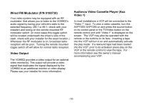
Audiovox VOH802 Operation Manual - Page 13
Typical System Connections
 |
UPC - 044476741371
View all Audiovox VOH802 manuals
Add to My Manuals
Save this manual to your list of manuals |
Page 13 highlights
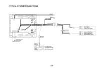
TYPICAL SYSTEM CONNECTIONS Yellow (Video out) Red (Audio Out R) White (Audio Out L) V1 VCP Antenna To FM Transmitter V2 DVD Accessory Harness 2 PIN IR Connector 4 PIN Power Connector Yellow RCA(Video) White RCA(Audio Left) Red RCA(Audio Right) Speaker or Headphone connection PIN 1 - Power/Red PIN 2 - Power GND/Black PIN 3 - Audio(L)Out/Grey PIN 4 - Audio GND/Black PIN 5 - Audio(R)Out /Green -13-
-
 1
1 -
2
-
3
-
4
-
5
-
6
-
7
-
 8
8 -
 9
9 -
 10
10 -
 11
11 -
 12
12 -
 13
13 -
 14
14 -
 15
15
 |
 |

TYPICAL SYSTEM CONNECTIONS
-13-
Yellow (Video out)
Red (Audio Out R)
White (Audio Out L)
Yellow RCA(Video)
White RCA(Audio Left)
Red RCA(Audio Right)
4 PIN
Power
Connector
2 PIN IR
Connector
Accessory
Harness
V1
VCP
V2
DVD
PIN
3 –
Audio(L)Out/Grey
PIN
4 –
Audio GND/Black
PIN
5 –
Audio(R)Out /Green
PIN
1 –
Power/Red
PIN
2 –
Power GND/Black
Speaker or Headphone
connection
To FM Transmitter
Antenna