Axis Communications 291 1U 291 1U Video Server Rack - Guida all'installazione - Page 4
AXIS 291 1U Video Server Rack - Overview, Placement requirements, Placement on a shelf/table
 |
View all Axis Communications 291 1U manuals
Add to My Manuals
Save this manual to your list of manuals |
Page 4 highlights
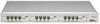
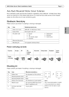
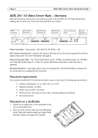
Page 4 AXIS Video Server Rack Installation Guide AXIS 291 1U Video Server Rack - Overview Read the following information to familiarize yourself with the AXIS 291 1U Video Server Rack, making note of where the connectors and indicators are located. Power Connector I/O Terminal Connector 3 I/O Terminal Connector 2 I/O Terminal Connector 1 Power & Network LEDs Network Connector Power Connector - Input power: 100-240V AC, 50-60 Hz, 1.9A I/O Terminal Connector(s) - provides the physical interface to the functions supported by the Axis blade video server. For more information see page 8. Power & Network LEDs - The 10/100 LED flashes red for 10 Mbit, and flashes green for 100 Mbit. The 1000 LED flashes green for 1 Gbit. The power LED shows steady green when the rack is powered. Network Connector - Axis blade video servers are designed for 10/100/1000 Mbps networks and are connected via a standard RJ-45 connector. Placement requirements The location the AXIS 291 1U Video Server Rack is used in must meet the following requirements: • Ambient temperature: 0° to +45°C (32° to 113°F) • Relative humidity: 20-80% • Power source within 1.8 meters • Minimum 5cm free space on each side, to ensure adequate ventilation • No excessive dust Placement on a shelf/table 1. Attach the 4 rubber feet to the underside of the unit, as illustrated here. 2. Place on a flat surface. Note that the AXIS Video Server Rack with cables weighs up to 6kg. Check that the surface can support this weight.
-
 1
1 -
 2
2 -
 3
3 -
 4
4 -
 5
5 -
 6
6 -
 7
7 -
 8
8 -
 9
9 -
 10
10 -
11
-
12
-
13
-
14
-
15
-
16
-
17
-
18
-
19
-
20
-
21
-
22
-
23
-
24
-
25
-
26
-
27
-
28
-
29
-
30
-
31
-
32
-
33
-
34
-
35
-
36
-
37
-
38
-
39
-
40
-
41
-
42
-
43
-
44
-
45
-
46
-
47
-
48
-
49
-
50
-
51
 |
 |
