Axis Communications M2014-E M2014-E Network Camera - User Manual - Page 5
Connectors and Buttons - network camera
 |
View all Axis Communications M2014-E manuals
Add to My Manuals
Save this manual to your list of manuals |
Page 5 highlights
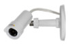
AXIS M2014-E Network Camera Hardware Overview Hardware Overview 1 23 8 9 10 11 4 5 67 12 13 14 15 1 Power indicator LED 2 Status indicator LED 3 Network indicator LED 4 SD card slot (microSD card) 5 RJ12 connector 6 I/O connector 7 Main unit 8 Network connector (PoE) 9 Control button 10 Power connector 11 Mounting rail 12 Camera unit 13 Stand 14 Stand extension 15 Mounting clamp Connectors and Buttons For technical specifications, see page 48. Network Connector RJ45 Ethernet connector with Power over Ethernet (PoE). 5
-
 1
1 -
 2
2 -
 3
3 -
 4
4 -
 5
5 -
 6
6 -
 7
7 -
 8
8 -
 9
9 -
 10
10 -
 11
11 -
12
-
13
-
14
-
15
-
16
-
17
-
18
-
19
-
20
-
21
-
22
-
23
-
24
-
25
-
26
-
27
-
28
-
29
-
30
-
31
-
32
-
33
-
34
-
35
-
36
-
37
-
38
-
39
-
40
-
41
-
42
-
43
-
44
-
45
-
46
-
47
-
48
-
49
-
50
-
51
-
52
 |
 |

AXISM2014–ENetworkCamera
HardwareOverview
HardwareOverview
1
PowerindicatorLED
2
Status indicator LED
3
NetworkindicatorLED
4
SDcardslot(microSDcard)
5
RJ12 connector
6
I/O connector
7
Main unit
8
Networkconnector(PoE)
9
Control button
10 Power connector
11 Mounting rail
12 Camera unit
13 Stand
14 Stand extension
15 Mounting clamp
Connectors and Buttons
For technical specifications, see
page48
.
Network Connector
RJ45 Ethernet connector with Power over Ethernet (PoE).
5