Behringer 182 SEQUENCER Quick Start Guide - Page 2
Power Connection, Installation, Specifications
 |
View all Behringer 182 SEQUENCER manuals
Add to My Manuals
Save this manual to your list of manuals |
Page 2 highlights
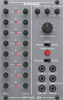
Power Connection Speci cations Inputs Tempo CV input Type 3.5 mm TS jack, DC coupled Impedance 100 kΩ, unbalanced Max input level +10 V CV scaling 1 V/oct. The 182 ANALOG SEQUENCER module comes with the required power cable for connecting to a standard Eurorack power supply system. Follow these steps to connect power to the module. It is easier to make these connections before the module has been mounted into a rack case. Trigger input Type Impedance Max input level Outputs 3.5 mm TS jack, DC coupled 30 kΩ, unbalanced +10 V 1. Turn the power supply or rack case power o and disconnect the power cable. 2. Insert the 16-pin connector on the power cable into the socket on the power supply or rack case. The connector has a tab that will align with the gap in the socket, so it cannot be inserted incorrectly. If the power supply does not have a keyed socket, be sure to orient pin 1 (-12 V) with the red stripe on the cable. CV output Type Impedance Max output level Gate output Type Impedance 2 x 3.5 mm TS jacks, DC coupled 600 Ω, unbalanced +5 V 3.5 mm TS jack, DC coupled 600 Ω, unbalanced 3. Insert the 10-pin connector into the socket on the back of the module. The connector has a tab that will align with the socket for correct orientation. 4. After both ends of the power cable have been securely attached, you may mount the module in a case and turn on the power supply. Max output level Trigger output Type Impedance Max output level Controls +5 V 3.5 mm TS jack, DC coupled 3 kΩ, unbalanced +5 V Installation Step CV level Tempo 0 V to +5 V 0.14 Hz to 33 Hz The necessary screws are included with the module for mounting in a Eurorack case. Connect the power cable before mounting. Depending on the rack case, there may be a series of xed holes spaced 2 HP apart along the length of the case, or a track that allows individual threaded plates to slide along the length of the case. The free-moving threaded plates allow precise positioning of the module, but each plate should be positioned in the approximate relation to the mounting holes in your module before attaching the screws. Hold the module against the Eurorack rails so that each of the mounting holes are aligned with a threaded rail or threaded plate. Attach the screws part way to start, which will allow small adjustments to the positioning while you get them all aligned. After the nal position has been established, tighten the screws down. Delay Gate time Step number Step switch Start/stop switch Parallel/series switch Power Power supply Current draw Physical Dimensions Rack units 0 to 10 s 10 % to 90 % duty cycle 1 to 8 steps Repeat / manual / single Momentary 8 step / 16 step Eurorack 30 mA (+12 V), 30 mA (-12 V) 43 x 81 x 129 mm (1.7 x 3.2 x 5.1") 16 HP Weight 0.17 kg (0.37 lbs) LEGAL DISCLAIMER Music Tribe accepts no liability for any loss which may be su ered by any person who relies either wholly or in part upon any description, photograph, or statement contained herein. Technical speci cations, appearances and other information are subject to change without notice. All trademarks are the property of their respective owners. Midas, Klark Teknik, Lab Gruppen, Lake, Tannoy, Turbosound, TC Electronic, TC Helicon, Behringer, Bugera, Auratone and Coolaudio are trademarks or registered trademarks of Music Tribe Global Brands Ltd. © Music Tribe Global Brands Ltd. 2020 All rights reserved. LIMITED WARRANTY For the applicable warranty terms and conditions and additional information regarding Music Tribe's Limited Warranty, please see complete details online at musictribe.com/warranty.
-
 1
1 -
 2
2
 |
 |
