Behringer AUTOCOM PRO-XL MDX1600 Manual - Page 7
The compressor
 |
View all Behringer AUTOCOM PRO-XL MDX1600 manuals
Add to My Manuals
Save this manual to your list of manuals |
Page 7 highlights
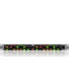
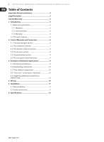
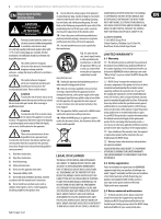
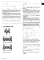
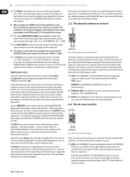
7 MULTICOM PRO-XL MDX4600/PRO-XL MDX2600/AUTOCOM PRO-XL MDX1600 User Manual Application hints The purpose of using an expander is usually to expand the usable dynamics towards the lower end, i.e. to improve the separation between low-level signals and the unavoidable noise floor by reducing the noise level. Start setting up the expander by turning the TRIGGER control from position OFF clockwise until the LEDs show the onset of the gain reduction. Preferrably, you should use some music material containing pauses and soft passages, so as to hear whether the beginnings or endings of words are cut off by the expander or are suppressed too much. If necessary, experiment with the release time or reduce the threshold a little bit. Gates work basically in the same way, the major difference being the fact that they reduce gain to a much greater extent. Once the level drops below threshold, the signal is muted completely. The classic application of a gate is the separation of signals delivered by multiple microphones in a multitrack recording. Especially when drums are recorded, a gate is almost indispensable to avoid crosstalk, e.g. of the cymbals into the floor tom microphones. However, you should always try to use the microphones and their directivity in the first place to achieve some degree of channel separation and hence a better and more natural result. Subsequently, a gate helps you optimize your set-up. The program-dependent IRC allows you to set both gate and expander easily and conveniently. Nevertheless, you should experiment with different release times and trigger settings to get a perfect result! 2.2 The compressor section (11)(12) (14)(19)(20) (6)(22)(10) (18)(21) MDX4600 (7) (9) (11) (14) (17) (19) (20) (6) (8)(10) (12) (13) (15) (16) (22) (18) (21) MDX4600 (7)(9) (11) (14) (19) (20) (6) (8)(10) (12) (13) (15) (16) (25) (18) (21) MDX1600 Fig. 2.3: Compressor section control elements (6) Use the THRESHOLD control to adjust the compressor threshold from -40 to +20 dB. (7) These three LEDs (AUTOCOM PRO‑XL and COMPOSER PRO‑XL only) indicate whether the input signal is above or below the adjusted compressor threshold. The yellow LED in the middle refers to the IKA "soft knee" range (if IKA is on). (8) Activating the SC EXT switch interrupts the link between the signal input and the compressor control section. At the same time, an external control signal can be fed in via the rear panel SC RETURN jack, taking over control of the input signal dynamics reduction. You can, for example, intensify the control function in a specific frequency range by inserting an equalizer via the SC SEND AND SC RETURN jacks. Detailed information on this special application can be found in chapter 3 "Examples of Sidechain Applications". This function, too, is only available on the AUTOCOM PRO-XL and COMPOSER PRO‑XL. (9) The SC MON switch links the sidechain input signal to the audio output, thereby muting the audio input signal. For example, this allows you to pre-monitor the sidechain signal in combination with an equalizer or other device inserted into the sidechain channel. The SC MONITOR function makes it easier to for example adapt the equalizer filters to the control signal. ◊ With the SC MONITOR switch activated, only the side-chain signal will be present at the output, which is shown by the flashing LED switch! (10) The RATIO control determines the ratio of input vs. output level with regard to all signals exceeding threshold by more than 10 dB. Although the compression starts earlier, the IKA characteristic ensures the smooth, inaudible onset of the gain reduction, which is why the ratio value will be reached only with 10 dB or more above threshold. It can be set continuously from 1:1 (no compression) to oo :1 (limiter). (11) The 12-digit GAIN REDUCTION display (MDX4600: 8-digit) informs you about the current gain reduction applied (1 to 30 dB). (12) The LO CONTOUR switch activates a high-pass filter in the side-chain path and thus avoids the "pumping" effect caused by high-energy bass frequencies and their influence on the compression process. (13) Use the ATTACK control to determine when the compression sets in once the signal has exceeded threshold (MDX1600 and MDX2600 only). The setting range is from 0.3 to 300 ms. (14) Press the INTERACTIVE KNEE switch to change from "hard knee" to IKA characteristic: Input signals exceeding threshold by up to 10 dB will be processed with a "soft knee" characteristic. Above 10 dB the control characteristic changes from "soft knee" to a more conventional "hard knee" compression. The IKA characteristic allows for a subtle and musical compression of the program material, and should be used whenever inaudible compression is desired. (15) The AUTO function, which is activated with the AUTO switch, disables the ATTACK and RELEASE controls and derives these time values automatically from the program material. It thus allows for a heavy and, at the same time, musical compression of signals with varying levels or of complex program material. (16) The RELEASE control (MDX1600 and MDX2600 only) sets the time when the original 1:1 gain is reached, after the signal has dropped below threshold again. The setting range is from 0.05 to 5 s. (17) Use the TUBE switch (MDX2600 only) to enhance the output signal with the warm and transparent tonal character typically produced by electronic tubes.
-
 1
1 -
 2
2 -
 3
3 -
 4
4 -
 5
5 -
 6
6 -
 7
7 -
 8
8 -
 9
9 -
 10
10 -
 11
11 -
 12
12 -
13
-
14
-
15
 |
 |