Behringer BASS V-AMP PRO Manual - Page 7
Application Examples, Operating Modes - footswitch
 |
View all Behringer BASS V-AMP PRO manuals
Add to My Manuals
Save this manual to your list of manuals |
Page 7 highlights
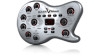
7 BASS V-AMP / BASS V-AMP PRO User Manual (24) The balanced stereo signal of your BASS V-AMP PRO can be taken at the DI OUT. This output should be connected to two balanced channel inputs on your mixing console. The signal level is set at +4 dBu in studio modes and at -10 dBu for live modes. (25) The connection to the inputs of an external stereo effects unit can be made using the POST DSP SEND (OUT) stereo output. The signal present at this output is identical to the signal at the digital outputs. In contrast to the SEND/LINE OUT connector (20), the signal is POST DSP here. In case both of the respective RETURN (IN) connectors (22) are not in use, the identical signal can be taken at the ANALOG LINE OUTPUTS (21). (26) BASS V-AMP PRO's signal can be digitally taken at the S/PDIF output. (27) The digital output signal of the BASS V-AMP PRO in AES/EBU format is found at the AES/EBU output (XLR connector), provided AES/EBU has been selected as output signal format (please adhere to the second note under (8) E). (28) Devices used to externally synchronize your BASS V-AMP PRO should be connected at the WORDCLOCK connector. This is a high-impedance connector, meaning that it has no internal terminal resistor (75 Ohm). (29) This is the MIDI OUT/THRU connector of the BASS V-AMP PRO. The connector is preconfigured in the MIDI Out setting at the assembly plant, but it can be switched to MIDI Thru (see (8) A). (30) A MIDI foot pedal, for example the BEHRINGER MIDI FOOT CONTROLLER FCB1010, can be connected at the MIDI IN connector. Please also read chapter 8.4. (31) SERIAL NUMBER. (32) FUSE RETAINER/VOLTAGE SELECTOR. Please make sure that the voltage indicated in the voltage selector maches the local voltage before you connect the unit to the mains. Always replace blown fuses with fuses of the same type. Some units feature a fuse retainer in which a selection between 230 V and 120 V is possible. Please beware: When using your unit outside of Europe on 120 V, a higher fuse rate is required (see chapter 8 "INSTALLATION"). (33) Power is supplied via an IEC connector. The matching cable is provided with the unit. 2.3 BASS V-AMP connectors (side) (21) The stereo output signal of your BASS V-AMP can be taken at the balanced LINE OUT connectors. (29) This is the MIDI OUT/THRU connector of the BASS V-AMP. The connector is configured to MIDI Out at the assembly plant, but it can be reconfigured to MIDI Thru (see (8) A). (30) A MIDI foot pedal (e.g. the BEHRINGER MIDI FOOT CONTROLLER FCB1010) can be connected to the MIDI IN connector. More on this subject in chapter 8.4. (33) Connect the power supply unit via the AC IN connector. When you plug the power supply unit in the mains, your BASS V-AMP is automatically switched on. (34) Connect the stereo jack of your footswitch FS112V to the FOOTSWITCH connector. This will enable you to alternate between different presets within a preset bank. When you keep the DOWN button on the footswitch pressed for longer than two seconds, this automatically powers up the tuner. Doing the same again alternately turns the tuner off. (35) The volume of the signal fed into the AUX IN input is adjusted by using the AUX LEVEL control. (36) By using the AUX IN jack input, you can feed an additional stereo signal into your BASS V-AMP. This way, you can play along to a drum computer or a playback. 3. Application Examples/ Operating Modes To optimally adapt your BASS V-AMP/BASS V-AMP PRO to various studio and/ or live situations, you may choose between six different operating modes (CONFIGURATION, keys B and D in the case of BASS V-AMP as well as keys D and E in the case of BASS V-AMP PRO). These operating modes function independently from the settings already selected on the unit itself (i.e. how the output signal of your BASS V-AMP/BASS V-AMP PRO is taken). This way, the left and the right output signals can be used entirely differently. The table on the following page explains in full detail how you can tap into the signal at the output of your BASS V-AMP/BASS V-AMP PRO with or without a speaker simulation/EQ. Additionally, the effects signal at the output does not necessarily have to be identical for both sides (see table 3.1). 3.1 Selecting an operating mode (CONFIGURATION) Your BASS V-AMP/BASS V-AMP PRO is set to studio 1 (S1) operating mode when it leaves the assembly plant. To change this setting, select the CONFIGURATION mode. Please press the B and D keys at the same time (BASS V-AMP) or D and E (BASS V-AMP PRO). By using the arrow keys, you select between different operating modes. To exit this mode, press TUNER once. Various operating modes are described on the following pages in greater detail. To adjust the output level of your instrument, use a specific level control located at the beginning of the signal path. This way, it is possible to adjust the input sensitivity by +12/-6 dB (middle value = 0 dB): Please select the CONFIGURATION mode and adjust the desired sensitivity level by keeping the TAP key pressed and turning the GAIN control. ◊ A change in input gain has an effect on all presets. Therefore, use it with caution to allow for example an adjustment to instruments with strongly vary-ing signal levels. 3.2 Standard setup To use your BASS V-AMP/BASS V-AMP PRO at the practice room, connect the unit as described in fig. 1.4. and 2.3 of the included appendix. Instead of a bass, you can of course connect other musical instruments. Connect your headphones to the PHONES connector. By using the FS112V footswitch delivered with your BASS V-AMP/BASS V-AMP PRO, you can alternate between the five presets contained in a preset bank, or you can power up the tuner. Live modes L1 and L2 featured in figures 1.4, 1.5 and 2.4 are particularly well suited for more demanding live or practice room applications. By using a MIDI foot controller (fig. 1.4 and 2.5), you can alternate between different presets, banks and amps, the tuner etc. An additional stereo signal can be fed into your BASS V-AMP/BASS V-AMP PRO at the aux in (see fig. 1.3 and 1.5). Naturally, your BASS V-AMP/BASS V-AMP PRO is in its best shape when its bass parts are immortalized on an analog or digital recording medium. Its advantages are most apparent when used in recording situations. Your BASS V-AMP/ BASS V-AMP PRO gives you unsurpassed flexibility because you can simply take it with you into the control room and forget all about having to use speakers. This way, you have the best control of the sound of your BASS V-AMP/ BASS V-AMP PRO at all times. If you realize that you have to change the signal on the mixing console, you can work with the tone engineer on your sound so that the recording is done optimally, capturing your sound the way you want it. Simply put: no annoying back-and-forth trips between studio and control room.
-
 1
1 -
 2
2 -
 3
3 -
 4
4 -
 5
5 -
 6
6 -
 7
7 -
 8
8 -
 9
9 -
 10
10 -
 11
11 -
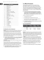 12
12 -
13
-
14
-
15
-
16
-
17
-
18
-
19
-
20
-
21
 |
 |