Behringer CX3400 Quick Start Guide - Page 5
Controls - super x pro
 |
View all Behringer CX3400 manuals
Add to My Manuals
Save this manual to your list of manuals |
Page 5 highlights
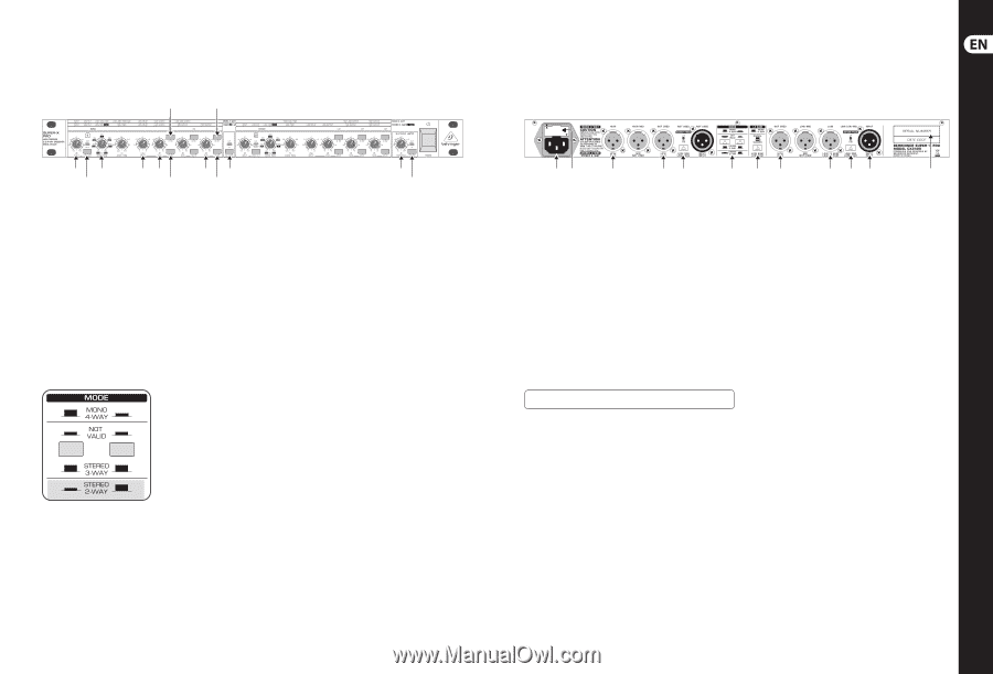
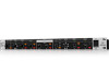
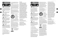
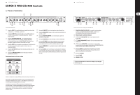
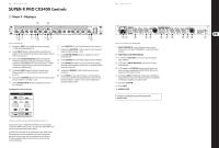
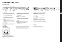
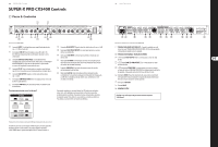
8 SUPER-X PRO CX3400 SUPER-X PRO CX3400 Controls (EN) Step 2: Controls (6) (9) 9 Quick Start Guide (1) (3) (4) (5) (8) (11) (12) (2) (7) (10) (13) The front panel of the SUPER-X PRO (1) INPUT control. This control adjusts the input gain from +12 to -12 dB. (7) LOW MUTE button. Mutes the Low band. (2) LOW CUT button. This button activates the 25 Hz highpass filter protecting (8) HIGH OUTPUT control. Controls the output level of the High band from the woofers against low-frequency signals. +6 to -6 dB. (3) LOW/HIGH XOVER FREQ. control. This control governs the crossover frequency between the Low and High bands. When the XOVER FREQUENCY button on the rear of the unit is pressed, the frequency range is multiplied by the factor 10. (4) DELAY control. This control delays the Low signal by as much as 2 ms, which is useful to align the speaker systems in phase. (5) LOW OUTPUT control. Controls the output level of the Low band from +6 to -6 dB. (6) LOW PHASE INVERT button. This button reverses the polarity of the Low output. (9) HIGH PHASE INVERT button. This button reverses the polarity of the High output. (10) HIGH MUTE button. Mutes the High band. (11) CD HORN button. This button provides a special form of frequency correction in the High band for constant-directivity horns. (12) THRESHOLD control. This control determines the limiter threshold. (13) LIMITER button. This button activates all limiters. Whenever the signal surpasses the limiter threshold, the LIM-LEDs above the Gain control light up, signaling that the CX3400 cuts back the output level. Stereo 2-way operation (1) (2) (3) (5) (6) (8) (9) (10) (12) (13) (14) (15) Active control elements on the rear panel of the SUPER-X PRO for 2-way stereo operation (1) Use the enclosed power cord to connect the unit to the mains. (2) FUSE HOLDER / VOLTAGE SELECTOR. (3) and (10) HIGH OUTPUT connector. Output for the High band signal. (5) and (12) LOW (LF SUM) OUTPUT connector. Output for the Low band signal. (6) and (13) XOVER FREQ. button. This button serves to switch over the control range of the front-panel LOW/HIGH OVER FREQ. control from 44 to 930 Hz or 440 Hz to 9.3 kHz. (8) MODE button. In stereo 2-way mode, the first button must be pressed, the second released. Please observe the labels on the rear panel of the unit. (9) LOW SUM button. (14) INPUT connector. (15) SERIAL NUMBER. Check Out behringer.com for Full Manual Proper selection of the two MODE buttons for stereo 2-way operation First, activate stereo 2-way mode by means of the two MODE buttons on the rear panel. The STEREO-LED on the front panel, above the LOW CUT button in channel 2, lights up. Subsequently, the LEDs above the active controls on the front panel light up, signaling which controls are active in the operating mode you just selected. The functions of these controls can be seen from the second strip label. In stereo mode, both channels perform the same functions.
-
 1
1 -
 2
2 -
 3
3 -
 4
4 -
 5
5 -
 6
6 -
 7
7 -
 8
8 -
 9
9 -
 10
10 -
 11
11 -
12
-
13
 |
 |