Behringer EP2000 Manual - Page 11
Specifications - wiring
 |
View all Behringer EP2000 manuals
Add to My Manuals
Save this manual to your list of manuals |
Page 11 highlights
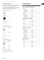
11 EUROPOWER EP4000/EP2000 User Manual 4.2 Audio connections Various cables are needed for different types of applications. The following illustrations show the correct wiring. Always use high-grade cables. When connecting a balanced input signal, please make sure to exclusively use balanced cables for passing the signal further on. Otherwise, one single unbalanced cable can turn the entire signal unbalanced. Balanced use with XLR connectors 21 3 input 1 = ground/shield 2 = hot (+ve) 3 = cold (-ve) 12 3 output For unbalanced use, pin 1 and pin 3 have to be bridged Fig. 4.3: XLR connectors Unbalanced ¼" TS connector strain relief clamp sleeve tip sleeve (ground/shield) tip (signal) Fig. 4.4: ¼" TS connector Balanced ¼" TRS connector strain relief clamp sleeve ring tip sleeve ground/shield ring cold (-ve) tip hot (+ve) For connection of balanced and unbalanced plugs, ring and sleeve have to be bridged at the stereo plug. Fig. 4.5: ¼" TRS connector 5. Specifications Output Power RMS @ 1% THD (Sine Wave), Both Channels Driven EP4000 8 Ω per channel 550 W 4 Ω per channel 950 W 2 Ω per channel 1250 W EP2000 8 Ω per channel 350 W 4 Ω per channel 500 W 2 Ω per channel 650 W RMS @ 1% THD (Sine Wave), Bridged Mode EP4000 8 Ω 1750 W 4 Ω 2400 W EP2000 8 Ω 1000 W 4 Ω 1300 W Peak Power, Both Channels Driven EP4000 8 Ω per channel 750 W 4 Ω per channel 1400 W 2 Ω per channel 2000 W EP2000 8 Ω per channel 400 W 4 Ω per channel 750 W 2 Ω per channel 1000 W Peak Power, Bridged Mode EP4000 8 Ω 2800 W 4 Ω 4000 W EP2000 8 Ω 1500 W 4 Ω 2000 W
-
 1
1 -
2
-
3
-
4
-
5
-
 6
6 -
 7
7 -
 8
8 -
 9
9 -
 10
10 -
 11
11 -
 12
12 -
 13
13 -
 14
14
 |
 |
