Behringer EUROPOWER EP2000 Quick Start Guide - Page 9
Controls - europower amp
 |
View all Behringer EUROPOWER EP2000 manuals
Add to My Manuals
Save this manual to your list of manuals |
Page 9 highlights
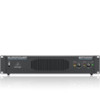
16 EUROPOWER EP4000/EP2000 EUROPOWER EP4000/EP2000 Controls (EN) Controls Since control elements of both the EP2000 and the EP4000 are identical, we have used the EP2000 as the model represented in the illustrations to assure simplicity. (1) The main switch is used to power up the amp. ◊ Merely switching the unit off does not mean that it is fully disconnected from the mains. When not using the unit for prolonged periods of time, please unplug the unit's power cord from the power outlet. (2) Ventilation openings are located at the front of the unit, so that hot air is prevented from being trapped inside the unit, thus causing faulty operation or even damage. (3) The CLIP LED lights up when the signal is distorted. Should distortion occur, reduce the input level, so that the CLIP LED stops lighting up. (4) The SIGNAL LED lights up as long as a signal is present at the input. (5) The Gain control (channels 1 and 2) is used for setting up the input gain. (6) The POWER LED lights up as soon as the unit is powered up. (7) These are the balanced XLR inputs (channels 1 and 2). (8) These are the stereo ¼" TRS inputs (channels 1 and 2). They can also be used with unbalanced plugs. (9) These are the MODE switches, used to alter the operating modes as well as to set the limiters and high-pass filters. (10) The unit's fan is located here. Fan speed adjusts automatically to assure trouble-free operation. ◊ To prevent faulty operation, please assure that the unit is kept at a distance from other appliances emanating heat. (11) These are the speaker outputs (channels 1 and 2). When running the unit in monobridged mode, please use the channel 1 output exclusively. (12) These are the output terminals (channels 1 and 2). When running in mono, please make sure to use both middle connectors to connect your loudspeaker. (13) BREAKER (automated fuse). After eliminating the cause of faulty operation, simply depress the BREAKER and power up the unit again. The BREAKER acts in place of common discardable fuses. !!Caution ◊ Before engaging the BREAKER switch, you should power down the unit (POWER switch set to OFF)! (14) Power is supplied via an IEC connector. The matching cable is provided with the unit. (15) SERIAL NUMBER of your EUROPOWER. (16) Here you can fi nd a detailed overview of the individual MODE SWITCHES functions ((9)). When running in mono-bridged mode, the voltage of both channels is added up and fed into a single loudspeaker system. There is one input and one output signal respectively, and only the controls of channel 1 (and not of channel 2) are used. ◊ However, should the DIP switches 4 and 5 still be in PARALLEL INPUTS position while in mono-bridged mode, the signal on the free input (input channel 2) can be forwarded to an additional amp. Examples: • Driving a single 8-Ohm loudspeaker. • Driving a single 4-Ohm loudspeaker. Electric guitar V-AMP PRO Input channel 1 EUROPOWER EP2000 (Mono Bridged Mode) BG412F Mono-bridged mode ◊ When the amp is overdriven for longer periods of time, the output signal may occasionally be muted for several seconds. In certain situations, excessive overdriving may trigger off the automated fuse. To avoid overdriving the amp, please continually make sure that an appropriate volume level is applied. 17 Quick Start Guide !!Caution ◊ 2-Ohm loads should never be applied when in mono-bridged mode. ◊ When connecting a balanced input signal, please make sure to exclusively use balanced cables for passing the signal further on. Otherwise, a single unbalanced cable can turn the entire signal unbalanced. Safety precautions for mono-bridged operation ◊ Running your amp in mono-bridged mode can quickly result in excessive overdriving and premature shutting down of the unit itself. In the worst-case scenario, your loudspeakers may be damaged permanently. Therefore, you should always make sure that the speakers you use can indeed handle the power load fed into them. ◊ A voltage of up to 100 V RMS is present between the output connectors of the EP4000. Always implement appropriate safety precautions when connecting your speakers to avoid the risk of electric shock. XENYX X2222USB Mixing Console L R Stereo out SUPER-X PRO CX2310 Crossover EUROPOWER EP2000 (Stereo Mode) Hi Lo EUROLIVE VP1220 Full range loudspeaker EUROPOWER EP2000 (Stereo Mode) Hi Lo EUROLIVE VP2520 Full range loudspeaker EUROPOWER EP2000 (Bridge Mode) Sub EUROLIVE VP1800S PRO Subwoofer Stereo bi-amp mode with a separate subwoofer
-
 1
1 -
2
-
3
-
 4
4 -
 5
5 -
 6
6 -
 7
7 -
 8
8 -
 9
9 -
 10
10 -
 11
11 -
 12
12 -
 13
13 -
 14
14 -
15
-
16
-
17
-
18
-
19
-
20
-
21
 |
 |
