Behringer EURORACK PRO RX1202FX Manual - Page 7
Stereo channels - 12
 |
View all Behringer EURORACK PRO RX1202FX manuals
Add to My Manuals
Save this manual to your list of manuals |
Page 7 highlights
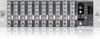
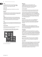
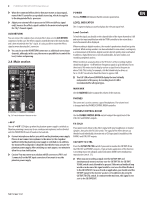
7 EURORACK PRO RX1202FX User Manual LINE IN Each mono input also features a balanced line input on a 1/4" connector. Unbalanced devices (mono connectors) can also be connected to these inputs. ◊ Please remember that you can only use either the microphone or the line input of a channel at any one time. You can never use both simultaneously! The MON path-as the name already implies-is meant to be used as monitor signal path. For this application, it is important that the controller works as pre-fader, which means it does not rely on the fader position. For this reason the AUX send path is unsuitable for the connection to effects devices. By using the MON controller, you can produce a mono mix of individual signals that can be routed over the MON plug, located on the backside, to a headphones amplifier (e.g. MINIAMP AMP800) or a power amplifier for monitoring. INSERT The INSERT connector is input and output at the same time. This allows you to insert external signal processors (compressors, gate, etc.) in the channel. The signal retrieval occurs after the TRIM and is practically a diversion of the signal. The input signal of the connected signal processor is diverted, processed and led back to the channel for further processing. TRIM Use the TRIM control to adjust the input gain. This control should always be turned fully counterclockwise whenever you connect or disconnect a signal source to one of the inputs. The scale has 2 different value ranges: the first value range (+10 to +60 dB) refers to the MIC input and shows the amplification for the signals fed in there. The second value range (+10 to -40 dBu) refers to the line input and shows its sensitivity. The settings for equipment with standard line-level signals (-10 dBV or +4 dBu) look like this: While the TRIM control is turned all the way down, connect your equipment. Set the TRIM control to the external devices' standard output level. If that unit has an output signal level display, it should show 0 dB during signal peaks. For +4 dBu, turn up TRIM slightly, for -10 dBV a bit more. Tweaking is done using the CLIP LED. PAN The PAN control determines the position of the channel signal within the stereo image. This control features a constant-power characteristic, which means the signal is always maintained at a constant level, irrespective of position in the stereo panorama. CLIP The CLIP LEDs of the mono channels illuminate when the input signal is driven too high, which could cause distortion. If this happens, use the TRIM control to reduce the preamp level until the LED does not light anymore. Channel fader The channel fader determines the level of the channel signal in the Main Mix. ◊ Caution: The channel fader needs to be open so that the effects processor receives a signal from this channel because the FX bus to the effects processor is switched to post-fader! 2.2 Stereo channels HIGH/LOW All mono input channels include a 3-band equalizer. All bands provide boost or cut of up to 15 dB. In the central position, the equalizer is inactive. The upper (HIGH) and the lower band (LOW) are shelving filters that increase or decrease all frequencies above or below their cut-off frequency. The cut-off frequencies of the upper and lower band are 12 kHz and 80 Hz respectively. MON/FX FX send buses (or AUX send buses) enable you to extract signals from one or more channels and collect these on a bus. You can retrieve the signal at the send connector to direct it to an external effects device, for example. The AUX return input is used as the return path. The send buses of the RX1202FX are mono buses. As the name suggests, the FX sends of the EURORACK mixing consoles are intended to drive effects devices (reverb, delay, etc.) and are therefore configured post-fader. This means that the mix between dry signal and effect remains at the level determined by the channel's aux send, irrespective of the channel fader setting. If this were not the case, the effects signal of the channel would remain audible even when the fader is lowered to zero. In the RX1202FX, the FX send is routed directly to the built-in effects processor. To make sure that the effects processor receives an input signal, you shouldn't turn this control all the way to the left (-∞). Fig. 2.2: Connectors and controls on the stereo channels LINE IN Each stereo channel has two balanced line level inputs on 1/4" connectors for left and right channels. If only the connector marked "L" (left) is used, the channel operates in mono. The stereo channels are designed to handle typical line level signals. Both inputs will also accept unbalanced connectors.
-
 1
1 -
 2
2 -
 3
3 -
 4
4 -
 5
5 -
 6
6 -
 7
7 -
 8
8 -
 9
9 -
 10
10 -
 11
11 -
 12
12 -
13
-
14
-
15
-
16
-
17
 |
 |
