Behringer EURORACK UB1204FX-PRO Quick Start Guide - Page 8
Controls - how to use
 |
View all Behringer EURORACK UB1204FX-PRO manuals
Add to My Manuals
Save this manual to your list of manuals |
Page 8 highlights
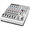
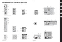
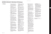
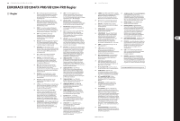
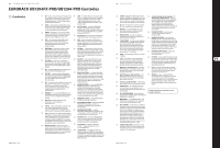
14 EURORACK UB1204FX-PRO/UB1204-PRO EURORACK UB1204FX-PRO/UB1204-PRO Controls (EN) Controls (1) MIC - Each mono input channel offers a balanced microphone input via the XLR connector and also features a switchable +48 V phantom power supply for condenser microphones. (2) LINE - IN Each mono input also features a balanced line input on a 1/4" connector. Unbalanced devices (mono jacks) can also be connected to these inputs. (3) LOW CUT - The mono channels of the mixing consoles have a high-slope LOW CUT filter for eliminating unwanted, low-frequency signal components (75 Hz, 18 dB/octave). (19) AUX SEND 1 - If you use aux send 1 pre-fader, you would usually connect the AUX SEND 1 connector to monitors via a power amp (or an active monitor system). If you use aux send 1 post-fader, proceed as described under aux send 2. (20) AUX SEND 2 - The AUX SEND 2 connector outputs the signal you picked up from the individual channels using the FX control. You can connect this to the input of an effects device in order to process the FX bus signal. Once an effects mix is created, the processed signal can then be routed from the effects device output back into the STEREO AUX RETURN connectors. (4) GAIN - Use the GAIN control to adjust the input gain. This control should always be turned fully counterclockwise whenever you connect or disconnect a signal source to one of the inputs. (5) EQUALIZER - All mono input channels include a 3-band equalizer. All bands provide boost or cut of up to 15 dB. In the central position, the equalizer is inactive. (6) AUX 1 (MON) - In the UB1204FX-PRO, aux send 1 can be switched pre-fader and is thus particularly suitable for setting up monitor mixes. In the UB1204-PRO, the first aux send is labeled MON and is permanently switched pre-fader. (7) PRE - When the PRE switch is pressed, aux send 1 is sourced pre-fader. (8) AUX 2 (FX) - The aux send labeled FX is for sending to effects devices and is thus set up to be post-fader. In the UB1204FX-PRO, the FX send is routed directly to the built-in effects processor. (9) PAN - The PAN control determines the position of the channel signal within the stereo image. This control features a constant-power characteristic, which means the signal is always maintained at a constant level, irrespective of position in the stereo panorama. (10) MUTE/ALT 3-4 - You can use the MUTE/ALT 3-4 switch to divert the channel from the main mix bus to the Alt 3-4 bus. This mutes the channel from the main mix. (11) MUTE LED - The MUTE LED indicates that the relevant channel is diverted to the submix (Alt 3-4 bus). (12) CLIP LED - The CLIP LED lights up when the input signal is driven too high. In this case, turn down the GAIN control and, if necessary, check the setting of the channel EQ. (13) SOLO - The SOLO switch (UB1204FX-PRO only) is used to route the channel signal to the solo bus (Solo In Place) or to the PFL bus (Pre Fader Listen). This enables you to monitor a channel signal without affecting the main output signal. The signal you hear is sourced either before (PFL, mono) or after (solo, stereo) both the pan control and the channel fader. (14) CHANNEL INPUTS - Each stereo channel has two balanced line level inputs on 1/4" connectors for left and right channels. If only the connector marked "L" is used, the channel operates in mono. Stereo channels are designed to handle typical line level signals. (15) LEVEL - For level matching, the stereo inputs feature a LEVEL switch which selects between +4 dBu and -10 dBV. At -10 dBV (home-recording level), the input is more sensitive than at +4 dBu (studio level). (21) STEREO AUX RETURN 1 - The STEREO AUX RETURN 1 connectors generally serve as the return path for the effects mix generated using the post-fader aux send. This is where you connect the output signal of the external effects device. If only the left connector is used, the AUX RETURN automatically operates in mono. (22) STEREO AUX RETURN 2 - The STEREO AUX RETURN 2 connectors serve as the return path for the effects mix generated using the FX control. If these connectors already function as additional inputs, you can route the effects signal back into the console via a different channel, with the added benefit that the channel EQ can be used to adjust the frequency response of the effects return signal. (23) STEREO AUX RETURN 1 - STEREO AUX RETURN 1 is a stereo control which determines the level of the signal in the main mix. (24) STEREO AUX RETURN MON - The STEREO AUX RETURN MON control has a special function: it can be used to add an effect to a monitor mix. (25) STEREO AUX RETURN 2 (FX) - The STEREO AUX RETURN 2 control determines the level of signals fed into the AUX RETURN 2 connectors which are routed to the main mix. (26) MAIN MIX/ALT 3-4 - The MAIN MIX/ALT 3-4 switch routes the signal connected to STEREO AUX RETURN 2 to either main mix (not pressed) or submix (Alt 3-4, pressed). (27) 2-TRACK INPUT - The 2-TRACK INPUT RCA connectors are provided for connecting a 2 track machine (e.g. DAT recorder). They can also be used as stereo line input. (28) 2-TRACK OUTPUT - These connectors are wired in parallel with the MAIN OUT and carry the main mix signal (unbalanced). Connect the 2-TRACK OUTPUT to the inputs of your recording device. The final output level can be adjusted via the high-precision MAIN MIX fader. (29) 2-TRACK - The 2-TRACK switch routes the signal from the 2-TRACK IN connectors to the level meter, the CONTROL ROOM OUT outputs and the PHONES connector this is a simple way to check recorded signals via monitor speakers or headphones. (30) ALT 3-4 - Similarly, the ALT 3-4 switch routes the signal from the Alt 3-4 bus to the same path for monitoring purposes. (31) MAIN MIX - The MAIN MIX switch sends the main mix signal to the above-mentioned outputs and to the level meter. (16) AUX SEND 1 (MON) - The AUX SEND control MON acts as (32) PHONES/CTRL RM - Use this control to set control room master control for aux send 1 and determines the level output level and headphones volume respectively. of the summed signal. In the UB1204FX-PRO, the MON control is called AUX SEND 1. (33) 2-TRACK TO MAIN - When the 2-TRACK TO MAIN switch is depressed, the 2-track input is routed to the main mix (17) AUX SEND 2 (FX) - Similarly, the FX control (AUX SEND 2) determines the level for aux send 2. and thus serves as an additional input for 2-track machines. You can also connect MIDI instruments or other signal sources here that do not require any further (18) SOLO - You can use the SOLO switch processing. At the same time, this switch disables the (UB1204FX-PRO only) to separately monitor the main mix to 2-TRACK OUTPUT link. aux sends via the CONTROL ROOM/PHONES outputs and check these with the level meters. 15 Quick Start Guide (34) POWER - The blue POWER LED indicates that the device is switched on. (35) +48 V - The red "+48 V" LED lights up when the phantom power supply is switched on. The phantom power supply is necessary for condenser microphones and is activated using the switch on the rear of the device. (36) MODE (UB1204FX-PRO only) - The MODE switch determines whether the channels' SOLO switch operates as PFL (Pre Fader Listen) or as solo (Solo In Place). (37) MAIN SOLO (UB1204FX-PRO only) - The MAIN SOLO LED lights up as soon as a channel or aux send solo switch is pressed. The MODE switch also has to be set at "Solo". (38) PFL (UB1204FX-PRO only) - The PFL LED indicates that the peak meter is set to PFL mode. (49) FX FOOTSW - Connect a standard foot switch to the foot switch connector; use this to switch the effects processor on and off. A dot at the bottom of the display indicates if the effects processor is muted via the foot switch. (50) LEVEL - The LED level meter on the effects module should display a sufficiently high level. Take care to ensure that the clip LED only lights up at peak levels. (51) PROGRAM - You can select the effect preset by turning the PROGRAM control. The display flashes the number of the current preset. To recall the selected preset, press the button; the flashing stops. You can also recall the selected preset with the foot switch. Check Out behringer.com for Full Manual (39) PHONES - You can connect headphones to this 1/4" TRS connector. The signal on the PHONES connection is sourced from the control room output. (40) ALT 3-4 AND MAIN MIX FADER - Use the highprecision quality faders to control the output level of the Alt 3-4 subgroup and main mix. (41) MAIN OUTPUTS - The MAIN outputs carry the MAIN MIX signal and are on balanced XLR connectors with a nominal level of +4 dBu. (42) ALT 3-4 OUTPUTS - The ALT 3-4 outputs are unbalanced and carry the signals of the channels that you have assigned to this group using the MUTE switch. This can be used to route a subgroup to a further mixing console for example, or or it could be used as a recording output working in tandem with the main output. This means you could record to four tracks simultaneously. The icing on the cake, so to speak, is that you could connect Y-cables to these four outputs and then connect your 8-track recorder in such a way that you have 2 x 4 tracks (e.g. channel 1 feeds track 1 and track 2, etc.). In the first recording pass, you record on tracks 1, 3, 5 and 7 and in the second pass, on tracks 2, 4, 6 and 8. (43) CONTROL ROOM OUTPUTS - The control room output is normally connected to the monitor system in the control room and provides the stereo mix or, when required, the solo signal. (44) FUSE HOLDER - The console is connected to the mains via the cable supplied which meets the required safety standards. Blown fuses must only be replaced by fuses of the same type and rating. (45) IEC MAINS RECEPTACLE - The mains connection is via a cable with IEC mains connector. An appropriate mains cable is supplied with the equipment. (46) POWER - Use the POWER switch to power up the mixing console. (47) PHANTOM - The PHANTOM switch activates the phantom power supply for the XLR connectors of the mono channels which is required to operate condenser microphones. The red +48 V LED lights up when phantom power is on. As a rule, dynamic microphones can still be used with phantom power switched on, provided that they are wired in a balanced configuration. In case of doubt, contact the microphone manufacturer! (48) 24-BIT MULTI-EFFECTS PROCESSOR - Here you can find a list of all presets stored in the multi-effects processor.
-
 1
1 -
2
-
 3
3 -
 4
4 -
 5
5 -
 6
6 -
 7
7 -
 8
8 -
 9
9 -
 10
10 -
 11
11 -
 12
12 -
 13
13 -
14
-
15
-
16
-
17
 |
 |