Behringer EURORACK UB1204FX-PRO Manual - Page 11
Digital Effects Processor - mixer manual
 |
View all Behringer EURORACK UB1204FX-PRO manuals
Add to My Manuals
Save this manual to your list of manuals |
Page 11 highlights
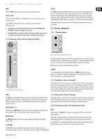
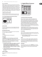
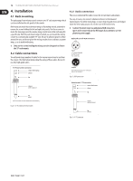
11 EURORACK UB1204FX-PRO/UB1204-PRO User Manual ALT 3-4 OUTPUTS The ALT 3-4 outputs are unbalanced and carry the signals of the channels that you have assigned to this group using the MUTE switch. This can be used to route a subgroup to a further mixing console for example, or or it could be used as a recording output working in tandem with the main output. This means you could record to four tracks simultaneously. The icing on the cake, so to speak, is that you could connect Y-cables to these four outputs and then connect your 8-track recorder in such a way that you have 2 x 4 tracks (e.g. channel 1 feeds track 1 and track 2, etc.). In the first recording pass, you record on tracks 1, 3, 5 and 7 and in the second pass, on tracks 2, 4, 6 and 8. 3. Digital Effects Processor CONTROL ROOM OUTPUTS The control room output is normally connected to the monitor system in the control room and provides the stereo mix or, when required, the solo signal. 2.4.2 Voltage supply, phantom power and fuse Fig. 3.1: Digital effects module (only UB1204FX-PRO) 24-BIT MULTI-EFFECTS PROCESSOR Fig. 2.15: Voltage supply and fuse FUSE HOLDER Here you can find a list of all presets stored in the multi-effects processor. This built-in effects module produces high-grade standard effects such as reverb, chorus, flanger, delay and various combination effects. The integrated effects module has the advantage of requiring no wiring. This way, the danger of creating ground loops or uneven signal levels is eliminated at the outset, completely simplifying the handling. You can route signals to the effects processor via aux send 2 in the channels and the aux send 2 master control. The built-in stereo effects processor has the advantage that it does not need to be cabled up. This eliminates any danger of hum or level mismatch right from the start providing straight-forward operation. The console is connected to the mains via the cable supplied which meets the required safety standards. Blown fuses must only be replaced by fuses of the same type and rating. IEC MAINS RECEPTACLE The mains connection is via a cable with IEC mains connector. An appropriate mains cable is supplied with the equipment. POWER These effect presets are designed to be added to dry signals. If you move the STEREO AUX RETURN FX control, you mix the channel signal (dry) and the effect signal. You can control the balance between the two signals with the channel fader and the STEREO AUX RETURN FX control. FX FOOTSW Connect a standard foot switch to the foot switch connector; use this to switch the effects processor on and off. A dot at the bottom of the display indicates if the effects processor is muted via the foot switch. Use the POWER switch to power up the mixing console. PHANTOM The PHANTOM switch activates the phantom power supply for the XLR connectors of the mono channels which is required to operate condenser microphones. The red +48 V LED lights up when phantom power is on. As a rule, dynamic microphones can still be used with phantom power switched on, provided that they are wired in a balanced configuration. In case of doubt, contact the microphone manufacturer! ◊ On the following page, you will find an illustration showing how to connect your foot switch correctly. LEVEL The LED level meter on the effects module should display a sufficiently high level. Take care to ensure that the clip LED only lights up at peak levels. If it is lit constantly, you are overloading the effects processor and this could cause unpleasant distortion. The FX control (AUX SEND 2) determines the level that reaches the effects module. ◊ After the phantom power supply has been switched on, do not connect microphones to the mixer (or the stagebox/wallbox). Connect the microphones before you switch phantom power on. In addition, the monitor/PA loudspeakers should be muted before activating the phantom power supply. After switching on, wait approx. one minute to allow the system to stabilize. PROGRAM You can select the effect preset by turning the PROGRAM control. The display flashes the number of the current preset. To recall the selected preset, press the button; the flashing stops. You can also recall the selected preset with the foot switch. ◊ Caution! You must never use unbalanced XLR connectors (PIN 1 and 3 connected) on the MIC input connectors if you want to use the phantom power supply. SERIAL NUMBER Please note the important information on the serial number given in chapter 1.3.3.
-
 1
1 -
2
-
3
-
4
-
5
-
 6
6 -
 7
7 -
 8
8 -
 9
9 -
 10
10 -
 11
11 -
 12
12 -
 13
13 -
 14
14 -
 15
15 -
 16
16
 |
 |