Behringer FBQ3102HD Quick Start Guide - Page 6
Controles, Controls
 |
View all Behringer FBQ3102HD manuals
Add to My Manuals
Save this manual to your list of manuals |
Page 6 highlights
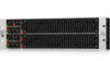
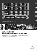
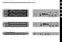
10 ULTRAGRAPH PRO FBQ6200HD/FBQ3102HD/FBQ1502HD 11 Quick Start Guide ULTRAGRAPH PRO FBQ6200HD/FBQ3102HD/FBQ1502HD Controls (EN) Controls (1) The INPUT/OUTPUT LEVEL METER lets you keep an (13) INPUT. These are the audio inputs of the FBQ3102. eye on the signal level in order to avoid distortion. All three equalizers in the series feature the same input Depending on the position of the I/O METER IN/OUT and output connectors in the form of balanced ¼" TRS switch (2) , the display shows either the input or the and XLR connectors. output signal (switch depressed) level. When the signal level reaches roughly +18 dB, that is, 3 dB below clipping starts to occur, the red CLIP LED lights up. (14) OUTPUT. These are the audio outputs. The ¼" connectors and their respective XLR connectors are wired in parallel. The level meter on the FBQ1502 displays only the output signal level. (15) SUB OUT. This balanced XLR connector provides the output signal for your subwoofer. A summed up mono (2) The I/O METER IN/OUT switch lets you alternate signal for the subwoofer is provided here. between displaying the input and the output signal level. When the switch is depressed, the output signal (16) Use the X-OVER FREQ control to select the desired level is shown. The FBQ1502 does not feature this switch. crossover frequency for the subwoofer. (3) When you press the FBQ switch, the FBQ feedback detection system is activated. The frequency (or frequencies) that evoke feedback is/are indicated by (17) The ULTRAGRAPH PRO FBQ6200 features a built-in limiter for each channel. Use the LIMITER switch for its activation. means of a lighted fader LED. All other LEDs are toned (18) The limiter display informs you about the amount of down. Now, simply lower the respective frequency range gain reduction perfomed by the limiter. somewhat until you eliminate the feedback and the LED no longer lights up. (19) The limiter confines the signal to an adjustable (4) The AUDIO IN/OUT switch is used to enable or disable the entire equalizer section. The FBQ1502 does this electronically, while the FBQ3102 and the FBQ6200 feature a relay-driven hard bypass function. As long as the switch is not depressed or while the equalizer is not powered up, the inputs and the outputs are directly connected to one another. The AUDIO IN/OUT switch is signal level. Use the THRESHOLD control to adjust the threshold value of the limiter from -6 to +22 dB. When the control is in the "-6 dB" setting, the gain reduction is very pronounced; the more you turn the control toward "+22 dB", the gain reduction is lower. When the threshold control is in its right-most position, the limiter is not applied. used to alternate between A and B, i.e. to compare the (20) Activate the pink noise generator by using the original unprocessed signal with the processed signal. PINK NOISE switch. The built-in switch illumination (5) The INPUT control is used to adjust the input signal blinks red when the pink noise generator is activated. level. You can boost/attenuate the signal level from (21) Read off the noise generator's signal level on +15 to -15 dB. the LED display. (6) The LOW CUT control is used to adjust the lower cut-off frequency of your ULTRAGRAPH PRO. The high-pass filter (18 dB/oct.) covers the range between 10 and 400 Hz, whereby the filter lets the signal pass through unprocessed, when the control is in the 10 Hz position. The FBQ1502 features a switchable high-pass filter (LOW CUT) instead of a low cut control, and its cut-off frequency is 25 Hz. (7) The HIGH CUT control is used to adjust the upper cut-off frequency of your ULTRAGRAPH PRO. The low-pass filter (18 dB/oct.) covers the range between 2.5 and 30 kHz, whereby the filter lets the signal pass through unprocessed when the control is in the 30 kHz position. (22) Use the NOISE LEVEL control to adjust the volume of the pink noise you generate. (23) The LED display indicates the signal level present at the SUB OUT connector. (24) The signal level present at the subwoofer output connector can be adjusted by using the LEVEL control. (25) To activate the subwoofer output, please depress the SUBWOOFER switch. Check Out behringer.com for Full Manual (8) The RANGE switch lets you alternate between the maximum value of lowering/increasing of individual frequencies from 12 dB to 6 dB (switch depressed). (9) These are the 31 SLIDING CONTROLS (FBQ1502: 15 sliding controls per channel) for individual frequency bands. When in "0" position, the particular frequency range is not processed at all. To boost a frequency range, pull the sliding control upward; to attenuate, pull the sliding control downward. (10) The POWER switch powers up your ULTRAGRAPH PRO. The POWER switch should always be in the "Off" position when you are about to connect your FBQ to the mains. (11) The connection to the mains is done via a standard IEC connector. A matching cable is included. (12) SERIAL NUMBER. (ES) Controles (1) El MEDIDOR DEL NIVEL DE ENTRADA/SALIDA (10) El interruptor POWER conecta su ULTRAGRAPH PRO. le permite vigilar el nivel de señal para evitar la El conmutador POWER debe encontrarse en la distorsión por sobreconducción. Dependiendo de la posición de "apagado" (no presionado) cuando realice posición del interruptor I/O METER IN/OUT, el display la conexión a la red de corriente. muestra o bien el nivel de señal de entrada o la de salida (interruptor pulsado). Cuando el nivel de señal alcance aproximadamente los +18 dB, es decir, 3 dB por debajo de que empiece a haber cortes, (11) La conexión a red se realiza mediante una toma de tres espigas IEC. En el suministro se incluye un cable de red adecuado. el CLIP-LED rojo se encenderá. El display de distorsión del FBQ1502 muestra sólo los valores (12) NÚMERO DE SERIE. de la señal de salida. (13) INPUT. Son las entradas de audio de su FBQ3102. (2) El interruptor I/O METER IN/OUT le permite alternar entre mostrar e nivel de señal en la entrada o en la salida. Cuando el interruptor esté pulsado, se mostrará Los tres ecualizadores de esta serie disponen de los mismos conectores de entrada y salida en la forma de conectores balanceados de 6,3 mm TRS y XLR. el nivel de señal de salida. El FBQ1502 no dispone de (14) OUTPUT. Son las salidas de audio. Los conectores este interruptor. de 6,3 mm y sus conectores XLR respectivos están (3) Cuando presione el interruptor FBQ, el sistema cableados en paralelo. de detección de realimentación FBQ se activa. (15) SUB OUT. La señal de salida para el subwoofer está La frecuencia (o frecuencias) que evocan la situada en este conector balanceado XLR. Una señal realimentación está/n indicada/s por medio de mono es creada combinando los dos canales estéreo un LED iluminado. El resto de los LEDs estarán para el subwoofer. apagados. Simplemente tiene que ir reduciendo el rango de frecuencia respectivo hasta que elimine la realimentación y hasta que el LED se apague. (16) Use el control X-OVER FREQ para seleccionar el frecuencia crossover deseada para el subwoofer. (4) El interruptor AUDIO IN/OUT se utiliza para conectar o desconectar toda una sección del ecualizador en un canal de audio. El FBQ1502 lo hace electrónicamente, (17) El ULTRAGRAPH PRO FBQ6200 dispone de un limitador para cada canal. Use el interruptor LIMITER para activarlo. mientras que el FBQ3102 y el FBQ6200 disponen de una función de bypass por relés. Mientras que el interruptor no esté pulsado o mientras el ecualizador (18) El display del limitador le informa del nivel de reducción de ganancia que genera el limitador. no esté encendido, las entradas y salidas están (19) El limitador constriñe la señal a un nivel de señal directamente conectadas unas a otras. El interruptor ajustable. Use el control THRESHOLD para ajustar AUDIO IN/OUT se usa para alternar entre A y el nivel de umbral del limitador de -6 a +22 dB. B, es decir, para comparar la señal original no Cuando en control está en la posición de "+6 dB", procesada y la procesada. la reducción de ganancia es muy pronunciada; (5) El control de INPUT se usa para ajustar el nivel de señal de entrada. Puede incrementar/atenuar el nivel de señal de +15 a -15 dB. cuanto más gire el control hacia "+22 dB", la reducción de ganancia será menor. Cuando el control de umbral está girado totalmente hacia la derecha, el limitador está desconectado. (6) El control LOW/CUT se usa para ajustar la frecuencia de corte más baja de su ULTRAGRAPH PRO. El filtro de high-pass (18 dB/oct.) cubre el rango entre 10 y 400 Hz, mientras que el filtro permite a la señal no (20) Active el generador de ruido rosa usando el interruptor PINK NOISE. El interruptor parpadeará en rojo cuando el generador esté activado. procesada pasar cuando el control está en la posición (21) Vea el nivel de señal del generador de ruido rosa en el de 10 Hz. El FBQ1502 dispone de un filtro high-pass diplay de LEDs. contectable (LOW CUT) en lugar de un control de corte bajo, y su frecuencia de corte es de 25 Hz. (22) Utilice el control NOISE LEVEL para ajustar el volumen del ruido rosa que genere. (7) El control HIGH CUT se usa para ajustar la frecuencia de corte más alta de su ULTRAGRAPH PRO. El filtro low-pass (18 dB/oct.) cubre el rango entre 2,5 y 30 kHz, (23) El diplay LED del Subwoofer indica el nivel de señal presente en el conector de salida SUB OUT. mientras que el filtro permite a la señal no procesada pasar cuando el control está en la posición de 30 kHz. (24) El nivel de señal presente en el conector de salida del subwoofer puede ajustarse usando el control LEVEL. (8) El interruptor RANGE le permite alternar entre el valor máximo de aumentar/disminuir los rangos de frecuencia individuales entre 12 dB a 6 dB (interruptor pulsado). (25) Para activar la salida del subwoofer, pulse el interruptor SUBWOOFER. (9) Estos son los 31 SLIDING CONTROLS (FBQ1502: 15 controles de deslizamiento por canal) para rangos de frecuencia individuales. Cuando se encuentran en posición "0", el rango de frecuencia particular no se procesa. Para incrementar un rango de frecuencia, deslice el control hacia arriba; para atenuarlo, deslícelo hacia abajo. Si quiere acceder al manual de instrucciones completo, vaya a la página web behringer.com
-
 1
1 -
 2
2 -
 3
3 -
 4
4 -
 5
5 -
 6
6 -
 7
7 -
 8
8 -
 9
9 -
 10
10 -
 11
11
 |
 |
