Behringer HA4700 Manual - Page 4
Introduction, Control Elements - headphone amp
 |
View all Behringer HA4700 manuals
Add to My Manuals
Save this manual to your list of manuals |
Page 4 highlights
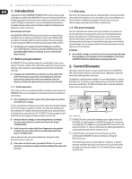
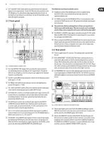
4 POWERPLAY PRO-8 HA8000/POWERPLAY PRO-XL HA4700 User Manual 1. Introduction Congratulations! With the BEHRINGER POWERPLAY PRO, you have acquired a highend headphone amplifier. Both POWERPLAY PRO units were developed with the most demanding applications in mind: professional recording, radio and television studios, as well as CD/digital sound production. They were developed as benchmark units for judging mixdown quality as well as distribution amplifiers for flexible playback applications in studio environments. Balanced inputs and outputs Both BEHRINGER POWERPLAY PROs feature electronically servo-balanced inputs and outputs. The servo function automatically recognizes when unbalanced pins are assigned. It internally modifies the nominal signal level, thus preventing any occurence of signal level difference between inputs and outputs (6 dB correction). ◊ The following user's manual is intended to familiarize you with the unit's control elements, so that you can master all the functions. After having thoroughly read the user's manual, store it at a safe place for future reference. 1.1 Before you get started The POWERPLAY PRO was carefully packed at the assembly plant to assure secure transport. Should the condition of the cardboard box suggest that damage may have taken place, please inspect the unit immediately and look for physical indications of damage. ◊ Damaged units should NEVER be sent directly to us. Please inform the dealer from whom you acquired the unit immediately as well as the transportation company from which you took delivery of the unit. Otherwise, all claims for replacement/repair may be rendered invalid. 1.1.1 Initial operation Please make sure the unit is provided with sufficient ventilation, and never place the POWERPLAY PRO on top of an amplifier or in the vicinity of a heater to avoid the risk of overheating. ◊ Before plugging the unit into a power socket, please make sure you have selected the correct voltage: The fuse compartment near the power plug socket contains three triangular markings. Two of these triangles are opposite one another. The voltage indicated adjacent to these markings is the voltage to which your unit has been set up, and can be altered by rotating the fuse compartment by 180°. ATTENTION: This does not apply to export models that were for example manufactured only for use with 120 V! ◊ If you alter the unit's voltage, you must change the fuses accordingly. The correct value of the fuses needed can be found in the chapter "TECHNICAL DATA". ◊ Faulty fuses must be replaced with fuses of appropriate rating without exception! The correct value of the fuses needed can be found in the chapter "TECHNICAL DATA". Power is delivered via the cable enclosed with the unit. All requiered safety precautions have been adhered to. ◊ Please make sure that the unit is grounded at all times. For your own protection, you should never tamper with the grounding of the cable or the unit itself. 1.2 Warranty Please take a few minutes and send us the completely filled out warranty card within 14 days of the date of purchase. You may also register online at www.behringer.com. The serial number needed for the registration is located at the top of the unit. Failure to register your product may void future warranty claims. 1.3 The user's manual This user's manual has been written in such a way to enable you an overview over the control elements of the unit and offers at the same time detailed information about possible applications. To facilitate quick look-ups, control elements have been described in groups depending on their function. Should you need detailed information about specific topics not covered in this manual, please visit our website at www.behringer.com. For example, additional information about power amps and effects processors is found there. ATTENTION! ◊ We would like to bring your attention to the fact that extremely loud sound levels may damage your hearing as well as your headphones. Please lower all OUTPUT LEVEL knobs leftwards before powering up the unit. 2. Control Elements This chapter contains descriptions of various control elements of your POWERPLAY PRO. All controls and connections are discussed in detail. Additionally, useful advice about their possible applications is also given. The HA8000 has eight independent amplifiers for connecting headphones, while the HA4700 has four. The latter has several additional features not found in the HA8000 due to space considerations. The differences between the two units are explained in detail in the text sections that follow. (3) (3) HA4700 HA8000 (1) (2) (2) Fig. 2.1: Input section (1) The DIRECT IN socket is used to feed in additional stereo signals. In the case of the HA4700, the signal brought in via the DIRECT IN input has the same priority as the MAIN signal. The HA8000 has a separate DIRECT INPUT connector for each channel (19) (see fig. 2.3). In the case of this model, the MAIN signal being fed in is automatically interrupted when the said input is in use. (2) The MASTER LEVEL control governs the level of the input signal that is fed through the MAIN INPUT connectors on the back or through the DIRECT IN connector. The HA8000 features two level controls (MAIN IN 1 / MAIN IN 2), so that two separately controllable input signals can be connected. You select which of the two signals is monitored by using the IN 1 / IN 2 switches (14) in the respective channel sections.
-
 1
1 -
 2
2 -
 3
3 -
 4
4 -
 5
5 -
 6
6 -
 7
7 -
 8
8 -
 9
9 -
 10
10
 |
 |