Behringer KM750 Quick Start Guide - Page 7
Step 2: Controls - professional
 |
View all Behringer KM750 manuals
Add to My Manuals
Save this manual to your list of manuals |
Page 7 highlights
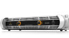
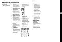
12 KM1700/KM750 KM1700/KM750 Controls (EN) Step 2: Controls (1) PROTECTION LED lights when the amplifier goes into thermal protection mode to cope with temperatures over 90°, or if the amplifier's functioning has become unstable. (12) TWIST- LOCKING SPEAKER OUTPUTS connect the amplifier to the speakers using professional speaker cables with twist-locking plugs. (2) SIG LED lights to indicate that a signal is present at the LED's respective channel input. (3) CLIP LED lights when the output signal exceeds the amplifier's clean headroom capacity. In normal operation, the CLIP LED may light from time to time, but should never light continuously. If the CLIP LED lights continuously, turn down the output level. (4) BRID LED lights to indicate that the amplifier's rear MODE switch has been set to BRIDGE mode. (5) POWER LED lights to indicate that the amplifier is powered on. (6) MONO LED lights to indicate that the amplifier's rear MODE switch has been set to (13) BINDING POST outputs accept bare wire connections from speaker cables. MONO mode. (14) GROUND LIFT switch can be used to (7) CH A/CH B CONTROLS adjust the input level. To increase signal gain, rotate the knobs clockwise; to reduce the gain, rotate the knobs counter-clockwise. eliminate humming caused by ground loops. When placed in the LIFT setting, the switch breaks the electrical connection between the shield/ground of the input signal and the power amp housing to eliminate (8) POWER switch turns the unit off and on. ground loops. In normal operation, set the (9) RACK EARS secure the unit into a rack using switch to the GND position. four attaching screws and washers (fasteners (15) LIMITER switch activates the internal limiter. not included). Requires two rack units. (16) MODE switch selects between MONO, STEREO, (10) VOLTAGE SELECTOR lets you match and BRIDGE operation modes. the amplifier to the local power system. Please ensure this switch corresponds to the actual power voltage available in your area. If in doubt, consult an electrician. (11) POWER SOURCE jack accepts the included IEC power cable. 2 2 2 13 Quick Start Guide (17) SENSITIVITY switch adjusts the input sensitivity versus the amplifier's rated output power. Choose between 0.77 V, 26 dB and 1.4 V settings. If using multiple KM amps, choose the 26 dB setting for equal output from all amplifiers. (18) INPUTS accept line-level input signals using balanced XLR, balanced ¼" TRS, or unbalanced ¼" TS connectors. (19) RCA INPUTS (KM750 only) accept unbalanced line-level signals using RCA connectors. (20) BREAKER (automated fuse, KM1700 only). After eliminating the cause of faulty operation, simply depress the BREAKER and power up the unit again. The BREAKER acts in place of common discardable fuses. BREAKER WARNING: Take the following actions BEFORE resetting the breaker: • Unplug the AC main cable • Move the POWER switch to the "OFF" position • Turn all input gain control elements down • And then, reset the breaker, connect the unit to the mains, switch ON and slowly increase the gain to the target volume
-
 1
1 -
 2
2 -
 3
3 -
 4
4 -
 5
5 -
 6
6 -
 7
7 -
 8
8 -
 9
9 -
 10
10 -
 11
11 -
 12
12 -
13
-
14
-
15
-
16
-
17
-
18
 |
 |
