Behringer MINIMIX MIX800 Manual - Page 5
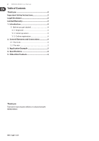
Application Example
 |
View all Behringer MINIMIX MIX800 manuals
Add to My Manuals
Save this manual to your list of manuals |
Page 5 highlights
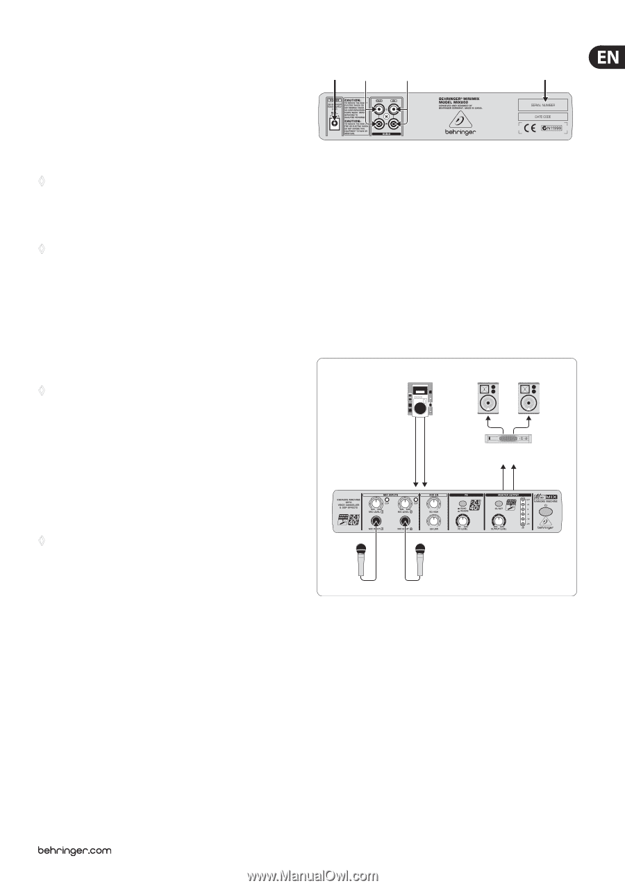
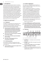
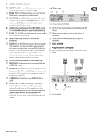
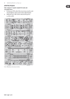
5 MINIMIX MIX800 User Manual (4) EQ LOW. The EQ LOW control allows you to raise or lower the low-frequency content of the microphone signal. (5) EQ HIGH. With the EQ HIGH control, you can raise or lower the high-frequency content of the microphone signal. (6) ECHO/REVERB. The MIX800 allows you to add an effect to the microphone signal. When the ECHO/REVERB button is pressed in, you can add REVERB to the signal. When the button is pressed out, the ECHO effect is active. ◊ 1 of the 2 effects is always active! Use the FX LEVEL control (7) to switch off the effect or to adjust the effect intensity. (7) FX LEVEL. The FX LEVEL control determines the amount of effect that is added to the master signal. ◊ Turn this control fully to the left to switch off the active effect. (8) IN/OUT. Press the IN/OUT button to activate the Voice Canceller in the signal path. This filter circuit allows you to remove the vocals almost completely from a recording. The filter has been designed so that vocal frequencies will be processed without significantly affecting other music signals. What is more, the filter only works in the center of the stereo panorama, where vocals are usually positioned in a recording. ◊ The Voice Canceller can be used for stereo signals only! (9) OUTPUT LEVEL. Set the volume of the output signal with the OUTPUT LEVEL control. (10) LED DISPLAY. The LED display is for monitoring the input level. It comprises 6 LEDs. When the Clip LED lights up, distortion may occur in the MIX800 output. Reduce the output level with the OUTPUT LEVEL control (9). (11) � SWITCH. The � switch turns your MINIMIX MIX800 on and off. ◊ Attention: The � switch does not fully disconnect the unit from the mains. To disconnect the unit from the mains, pull out the main cord plug or appliance coupler. When installing the product, ensure the plug or appliance coupler is readily operable. Unplug the power cord completely when the unit is not used for prolonged periods of time. 2.2 The rear (12) (13) (14) (15) Fig. 2.2: Rear panel connectors of the MIX800 (12) Use the 9 V jack to connect the power supply delivered with the unit. (13) These connectors are the unbalanced cinch outputs of the MIX800. (14) These connectors are the unbalanced cinch inputs of the MIX800. (15) SERIAL NUMBER. 3. Application Example The wiring example shown below gives you an idea of how to use the MIX800. CD-Player EUROLIVE B1520 PRO IN IN L R EUROPOWER EP2000 OUT OUT L R XM1800S Fig. 3.1: Using the MIX800
-
 1
1 -
 2
2 -
 3
3 -
 4
4 -
 5
5 -
 6
6 -
 7
7 -
 8
8
 |
 |