Behringer SONIC ULTRAMIZER SU9920 Quick Start Guide - Page 7
SONIC ULTRAMIZER SU9920 Controls
 |
View all Behringer SONIC ULTRAMIZER SU9920 manuals
Add to My Manuals
Save this manual to your list of manuals |
Page 7 highlights
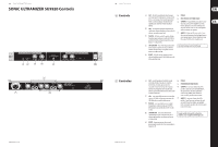
12 SONIC ULTRAMIZER SU9920 SONIC ULTRAMIZER SU9920 Controls (1) (2) (3) (4) (5) (8) (7) (9) 13 Quick Start Guide (EN) Controls (1) CLIP - This LED is constantly lit when the input (6) POWER. level is too high. If it lights up for a short period of time it is warning you of an impending overdrive. (7) FUSE HOLDER / IEC POWER SOCKET. There is a safety headroom of 3 dBu before the (8) OUTPUTS 1 - Balanced XLR sockets and ¼" jacks - signal becomes distorted. The LED should not these are used to connect amplifiers as well as light up. further signal processors and recording devices. (2) LEDs - The four LEDs display the output level in 10 dBu steps. Regular illumination of the 0 dBu LED The jacks and XLR sockets can be used in parallel when two outputs are required. indicates an optimal output level. (9) INPUTS 1 - Balanced XLR sockets and ¼" jacks - (3) PROCESS - With this control the portion of highfrequency signals to be processed by the SU9920 is specified. The MAX setting corresponds to a level these are used to connect line-level signal sources (e.g. a mixing console). To avoid interference only the jacks or the XLR sockets should be used. boost of +12 dbU at 5 kHz. (4) LOW CONTOUR - This control adjusts the portion of low-frequency signals to be processed by the SU9920. The MAX setting corresponds to a level boost of +12 dbU at 50 kHz. Check Out behringer.com for Full Manual (5) IN/OUT - With this switch signal processing is activated and deactivated. The LED lights up in the active operating mode. (6) (ES) Controles (1) CLIP - este LED permanece iluminado cuando (6) POWER. el nivel de entrada es muy alto. Si se ilumina brevemente, esto indica que la señal está (7) PORTAFUSIBLES/CONECTOR IEC. saturando. A manera de precaución, el aparato (8) OUTPUTS 1 - conectores balanceados XLR y dispone de un margen de sobrecarga de 3 dBu jack de 6,3 mm. Para conectar amplificadores, antes de que la señal empiece a distorsionar. El LED otros procesadores de señal y grabadores. no debería iluminarse. Si necesita dos salidas, puede utilizar los (2) LEDs - estos cuatro LEDs indican el nivel de salida conectores XLR y jack de manera paralela. en pasos de 10 dBu. La iluminación constante del (9) INPUTS 1 - conectores balanceados XLR y LED 0 dBu indica un nivel de salida óptimo. jack de 6,3 mm. Para conectar fuentes de señal (3) PROCESS - este control determina la cantidad de agudos que serán procesados por el SU9920. MAX equivale a un aumento de nivel de +12 dBu con nivel de línea (mezcladores, por ejemplo). Utilice únicamente uno de los dos conectores para evitar interferencias. a 5 kHz. (4) LOW CONTOUR - este control determina la cantidad de graves que serán procesados por el SU9920. MAX equivale a un aumento de nivel de +12 dBu a 50 Hz. Si quiere acceder al manual de instrucciones completo, vaya a la página web behringer.com (5) IN/OUT - botón para activar y desactivar el procesamiento de señal. Al activar el procesador se ilumina el LED.
-
 1
1 -
 2
2 -
 3
3 -
 4
4 -
 5
5 -
 6
6 -
 7
7 -
 8
8 -
 9
9 -
 10
10 -
 11
11 -
 12
12
 |
 |
