Behringer SONIC ULTRAMIZER SU9920 Manual - Page 8
Installation
 |
View all Behringer SONIC ULTRAMIZER SU9920 manuals
Add to My Manuals
Save this manual to your list of manuals |
Page 8 highlights
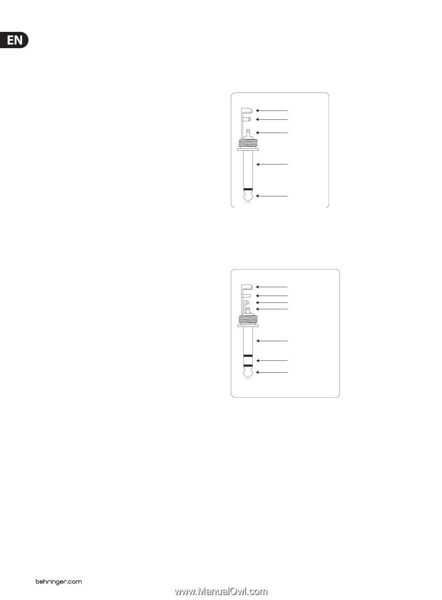
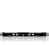
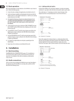
8 SONIC ULTRAMIZER SU9920 User Manual 3.2 Basic operation Due to the small number of control elements on the SU9920 it is easy to learn to use it. Perform the following steps: 1) Connect the unit according to the application as described in section 3.1. 2) Switch on all devices (amplifier and loudspeaker last) and ensure that the IN/OUT switch (5) on the SU9920 is illuminated, i.e. that the unit is working and all controls are set to 'MIN'. ◊ First make the following settings for one channel (channel 1 or 2) according to the input assignment. For stereo applications choose the same settings for the second channel as those made for the first channel. 3) Set the signal level on the device feeding the SONIC ULTRAMIZER such that the CLIP LED (1) on the SU9920 either does not light up at all or for a short period of time only. 4) Turn the PROCESS control (3) until the desired enhancement effect in the high-frequency range is achieved or the 0 dBU LED in the level display (2) lights up continuously. 5) Turn the LOW CONTOUR control (4) until the desired enhancement effect in the low-frequency range is achieved or the 0 dBu LED in the level display (2) lights up continuously. 6) To compare the original and processed signals, repeatedly press the IN/OUT button. 7) Repeat steps 4) to 6) until you are satisfied with the result. 4.2.1 Cabling with jack cables To operate the SU9920 in series with other equipment, you will need standard commercial ¼" jack cables, often referred to as instrument cables or patch cables. These cables have a ¼" TS jack plug at each end. Connect the inputs of the equipment with the corresponding outputs of each of the other devices. Unbalanced ¼" TS connector strain relief clamp sleeve tip sleeve (ground/shield) tip (signal) Fig. 4.1: Unbalanced ¼" TS jack plugs If your other equipment has balanced inputs, use a balanced switched cable with two stereo jack plugs at the balanced outputs of the SU9920. These cables provide a high level of security against interference signals such as noise interference from power cables, and they should be used for all long cable routes. 4. Installation 4.1 Rack mounting The BEHRINGER SONIC ULTRAMIZER SU9920 requires 1U for installation in a 19-inch rack. Please make sure that you leave around 10 cm for the rear connections. For installation of the unit in a rack please use M6 machine screws and nuts. 4.2 Audio connections There are various ways to integrate the SU9920 into your setup. Depending on the application you will need different connecting cables, and these will be discussed in the following section. Balanced ¼" TRS connector strain relief clamp sleeve ring tip sleeve ground/shield ring cold (-ve) tip hot (+ve) For connection of balanced and unbalanced plugs, ring and sleeve have to be bridged at the stereo plug. Fig. 4.2: Balanced ¼" TRS jack plugs
-
 1
1 -
2
-
 3
3 -
 4
4 -
 5
5 -
 6
6 -
 7
7 -
 8
8 -
 9
9 -
 10
10
 |
 |