Behringer SX3040 Manual - Page 8
Cabling with jack cables, Connection with insert cables - sonic
 |
View all Behringer SX3040 manuals
Add to My Manuals
Save this manual to your list of manuals |
Page 8 highlights
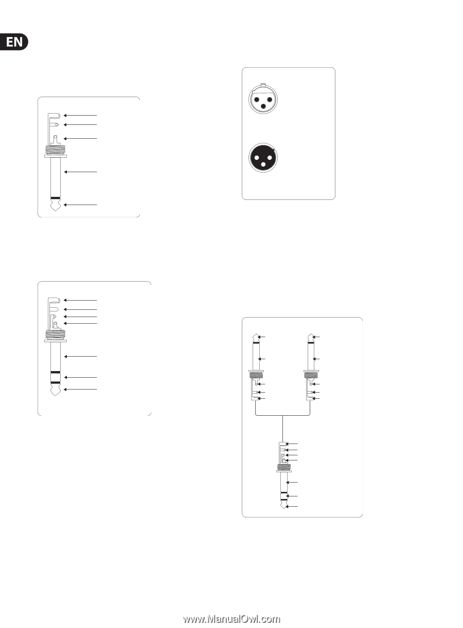
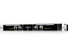
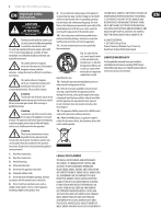
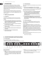
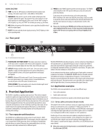
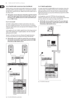
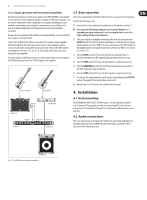
8 SONIC EXCITER SX3040 User Manual 4.2.1 Cabling with jack cables Alternatively, you can use professional XLR cables with an XLR socket on one side To operate the SX3040 in series with other equipment, you will need standard commercial ¼" jack cables, often referred to as instrument cables or patch cables. and an XLR plug on the other side. This cable connection is the most reliable both electrically and mechanically. These cables have a ¼" TS jack plug at each end. Connect the inputs of the equipment with the corresponding outputs of each of the other devices. Balanced use with XLR connectors Unbalanced ¼" TS connector strain relief clamp sleeve tip 21 3 input 1 = ground/shield 2 = hot (+ve) 3 = cold (-ve) sleeve (ground/shield) tip (signal) 12 3 output For unbalanced use, pin 1 and pin 3 have to be bridged Fig. 4.3: Balanced XLR plug Fig. 4.1: Unbalanced jack cable with ¼" TS jack plugs If your other equipment has balanced inputs, use a balanced switched cable with two stereo jack plugs at the balanced outputs of the SX3040. These cables provide a high level of security against interference signals such as noise interference from power cables, and should be used for all long cable routes. Balanced ¼" TRS connector strain relief clamp sleeve ring tip 4.2.2 Connection with insert cables Use standard ¼" insert cables to connect the SONIC EXCITER to the insert path of a mixing console. These Y cables have two ¼" TS connectors at one end, and one ¼" TRS connector at the other. Connect the plug marked "Send" to the INPUT L jack on the effects unit. Connect the "Return" plug to the OUTPUT L jack on the device. Connect the TRS connector to the insert jack of the channel strip on the mixing console. Use two insert cables for stereo sub-groups and main-mix inserts. The second cable must be connected to the INPUT/OUTPUT R jacks of the SX3040. Return (out) tip signal Send (in) tip signal sleeve ground/shield ring cold (-ve) tip hot (+ve) For connection of balanced and unbalanced plugs, ring and sleeve have to be bridged at the stereo plug. sleeve ground/shield sleeve ground/shield tip sleeve strain relief clamp tip sleeve strain relief clamp Fig. 4.2: Balanced jack cable with ¼" TRS jack plugs strain relief clamp sleeve ring tip sleeve ground/shield ring return (in) tip send (out) Fig. 4.4: Insert cable with one ¼" TRS (tip-ring-sleeve) jack plug on one end andtwo ¼" TS (tip-sleevel) jack plugs on the other end
-
 1
1 -
2
-
 3
3 -
 4
4 -
 5
5 -
 6
6 -
 7
7 -
 8
8 -
 9
9 -
 10
10
 |
 |