Behringer TUBE ULTRAGAIN MIC100 Manual - Page 14
Power Led, Db Pad, Phase Reverse, Limiter, Output, Serial Number
 |
View all Behringer TUBE ULTRAGAIN MIC100 manuals
Add to My Manuals
Save this manual to your list of manuals |
Page 14 highlights
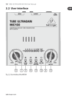
14 TUBE ULTRAGAIN MIC100 User Manual (6) The GAIN control allows applying gain from +26 to +60 dB to the input signal. This control should be set fully counterclockwise when (dis)connecting a sound source to the MIC100. When all connections are made, slowly start raising gain. (7) We recommend using the LED meter to adjust gain. The LED chain displays the output signal level in dB. Please make sure that the clip LED never lights up permanently. It should light up only at peak signals, but never all the time. (8) If your MIC100 is connected to the mains via the enclosed power supply unit, the POWER LED lights up to indicate that your MIC100 is running. (9) The 20 dB PAD button reduces the input sensitivity by 20 dB. The appropriate setting depends on the equipment connected. No matter what your application is, the clip LED warns you to reduce the gain setting, so as to avoid distortion. (10) This +48 V switch activates the phantom power supply for the XLR input. Phantom power supply is required for operating condenser microphones. (11) With the PHASE REVERSE switch, the input signal is reversed by 180°. This function is available for both mic and line signals. Use this function in a multi-microphone setup if you detect phase cancellations in specific frequency bands. (12) Use the LIMITER switch to limit the signal and to prevent distortion. (13) The OUTPUT control governs the output level of the device within a range from -∞ to +10 dB. If the control is set fully counter-clockwise, there is no output signal at all. The more the control is set clockwise, the higher the output level. The device's SERIAL NUMBER is found on the bottom side of the unit.
-
 1
1 -
2
-
3
-
4
-
5
-
6
-
7
-
8
-
 9
9 -
 10
10 -
 11
11 -
 12
12 -
 13
13 -
 14
14 -
 15
15 -
 16
16 -
 17
17 -
 18
18 -
 19
19 -
20
-
21
-
22
-
23
 |
 |
