Behringer ULTRA-DRIVE PRO DCX2496 Quick Start Guide - Page 7
ULTRADRIVE PRO DCX2496 Controls - ultradrive pro -
 |
View all Behringer ULTRA-DRIVE PRO DCX2496 manuals
Add to My Manuals
Save this manual to your list of manuals |
Page 7 highlights
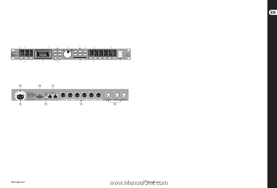
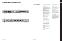
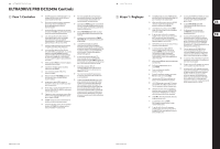
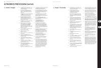
12 ULTRADRIVE PRO DCX2496 ULTRADRIVE PRO DCX2496 Controls (2) (1) (8) (7) (9) (6) (14) (13) (12) (3) (4) (5) (10) (11) (16) (15) (17) 13 Quick Start Guide (EN) Step 1: Controls (1) The DCX2496 features three 6-segment LED displays (plus CLIP and MUTE LED) for precise level adjustment of input signals A-C. (18) This is the FUSE HOLDER of your DCX2496. Blown fuses must be replaced by a fuse of the same type and rating. (2) If the input stage is overdriven, the CLIP LED will indicate that the signal is distorting. (19) The mains connection is an IEC receptacle. An appropriate power cord is included. (3) The bottom LED (#8) is the MUTE LED (red), which illumiates when the respective input is muted. (4) These are the input channel buttons, which allow you to activate specific functions from the selected menus (e.g. MUTE). Additionally, you can use these buttons to call up the IN A/B/C menus. (5) The DISPLAY shows all the menus available for preset editing. (6) Use these buttons to call up the DCX2496's menus (e.g. SETUP, RECALL, etc.). The only exception is the COMPARE button, which allows you to compare the edits made with the previously selected presets. When COMPARE is active, no value changes can be entered. (7) The PAGE buttons select single pages from one menu. (8) Individual parameters can be selected with the PARAM buttons. (9) The data wheel allows you to edit the selected parameters. (10) With the OK and CANCEL buttons you can either confirm or cancel any settings made. (20) The 9-pin RS-232 interface allows you to connect your DCX2496 to a computer. This enables you to save and load files, update the DCX2496 operating software, or remotely control one or several ULTRADRIVE PRO units from a PC. Free editor software can be downloaded at behringer.com. (21) When you have daisy-chained several ULTRADRIVE PRO via the LINK connectors (see (22)), please press the TERM switch on the first and last unit of the chain, to avoid data reflections and transmission errors. (22) Use the LINK connectors A and B (RS-485 network interface) and a commercially available network cable to daisy-chain several ULTRADRIVE PROs. (23) Balanced XLR output connectors for output channels 1-6. Connect your power amps here. (24) Balanced XLR input connectors A, B and C are used for connecting input signals. Input A can also be used for digital AES/EBU input signals. Input C can be used for line signals or for connecting a measuring microphone. If AUTO ALIGN has been enabled in the SETUP menu, input C will be set for mic levels automatically. Additionally, phantom power for the measuring microphone will be switched on. (11) The PCMCIA card slot is used to exchange files between your DCX2496 and a PC card with a flash memory. (12) Outputs 1-6 each have a six 5-segment LED display (plus MUTE, CLIP and LIMIT LED) showing the respective output levels. (13) Like the input stages, the output stages should not be overdriven, i.e. the CLIP LED should not illuminate. (14) The LIMIT LED illuminates when the limiter for the corresponding output has been activated and is operating. (15) The bottom LED indicator (#8) is the MUTE LED, which illuminates as soon as the corresponding output is muted. (16) Output channel buttons, with which you can enter the outputs 1-6 or mute or reactivate individual outputs in MUTE mode. (17) Use the POWER switch to put your DCX2496 into operation. The POWER switch should always be in the "Off" position when you are about to connect your unit to the mains.
-
 1
1 -
 2
2 -
 3
3 -
 4
4 -
 5
5 -
 6
6 -
 7
7 -
 8
8 -
 9
9 -
 10
10 -
 11
11 -
 12
12 -
13
-
14
-
15
-
16
-
17
 |
 |