Behringer ULTRABASS BVT5500H Manual - Page 10
System block diagram
 |
View all Behringer ULTRABASS BVT5500H manuals
Add to My Manuals
Save this manual to your list of manuals |
Page 10 highlights
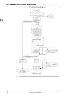
ULTRABASS BVT4500H/BVT5500H 8. System block diagram Fig. 8.1: BVT4500/5500H block diagram (Rectangles represent control elements, ovals represent jacks.) 10 System block diagram
-
 1
1 -
2
-
3
-
4
-
 5
5 -
 6
6 -
 7
7 -
 8
8 -
 9
9 -
 10
10 -
 11
11 -
 12
12
 |
 |

ULTRABASS BVT4500H/BVT5500H
System block diagram
10
System block diagram
8.
BVT4500/5500H block diagram (Rectangles represent control elements, ovals represent jacks.)
Fig. 8.1: