Behringer ULTRAPATCH PRO PX3000 Manual - Page 6
Wiring & Grounding, Cautions, Audio Connections, Specifications - ultramatch pro patchbay
 |
View all Behringer ULTRAPATCH PRO PX3000 manuals
Add to My Manuals
Save this manual to your list of manuals |
Page 6 highlights
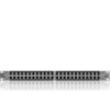
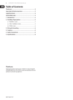
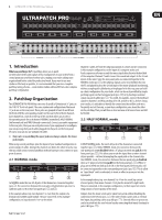
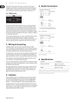
6 ULTRAPATCH PRO PX3000 User Manual The main left & right outputs of the mixer are connected, in this example configuration, to a mini-disc recorder. However, they can also be connected in parallel to another recorder (pos. (2) ). The mini-disc recorder can record other sources when they are connected to jack B of channels 15 and 16 (pos. (4) ) 2.3 THRU mode 5. Audio Connections Balanced ¼" TRS connector strain relief clamp sleeve ring tip A REAR FRONT B sleeve ground/shield This mode is for sound modules or playback devices (e.g. CD players) that only have output signals. You can save space by routing the left and right outputs to one channel (jacks A & B) of the patchbay. A more typical setup is to connect the left and right outputs to adjacent channels (jacks A & A) and then connect another device to jacks B & B of the same channels. This configuration also allows you to position the inputs and outputs of effects devices, compressors, equalizers, etc. directly above each other. In the example configuration above, the outputs of the playback devices (CD and mini-disc) plus the four individual outputs of a sampler are connected to channels 17 to 20, while channels 21 to 24 are used for the inputs & outputs of a compressor and an EQ, which are usually connected to the inserts of a mixer. ring cold (-ve) tip hot (+ve) For connection of balanced and unbalanced plugs, ring and sleeve have to be bridged at the stereo plug. Fig. 5.1: 1/4" TRS connector Unbalanced ¼" TS connector strain relief clamp sleeve tip 3. Wiring & Grounding Looming the wiring is an art itself and it is worth the time to get it right. First, it is important to avoid ground loops. Don't remove the ground connection of your mains cable plug to reduce 50/60 Hz mains hum. Instead, systematically disconnect the signal shields in the signal chain until the hum ceases. It is typically best to connect only one end of each shield to a central point and to connect this single point to ground. Then all equipment will be grounded via a single path (more than one path can lead to ground loops which can cause hum). Some equipment has isolated grounding for the signals and the mains. In this case, at least one screen should ground the equipment. Please assure that the patchbay is installed so that it does not disturb the studio's grounding scheme. Always use patch leads that are as short as possible and have the shield connected at both ends. After eliminating the mains hum from the system, make your cable looms from the patchbays outwards and use cable ties, flexible sheaths, multicores, etc. to keep the back of your racks orderly. It is also wise to keep low level/line level signal cables away from high voltage/mains cables. 4. Cautions Avoid routing digital signals near a patchbay because the pulse signal used for the transmission of digital signals causes heavy interference in analog signals. Do not use standard patchbays for digital signals. Use the ULTRAMATCH PRO SRC2496-it is specifically designed for routing and matching digital signals. Microphone inputs are for very low level signals and should never be routed via a patchbay. Plus, the +48 Volt phantom power from the mic input could damage other equipment. It is best to plug mics directly into the mixer or via a wall box using good quality balanced multi-core cables. sleeve (ground/shield) tip (signal) Fig. 5.2: 1/4" TS connector 6. Specifications Connectors Dimensions (H x W x D) Weight 1/4" TRS, balanced approx. 3 2/3 x 1 3/4 x 19" approx. 93 x 44.5 x 482.6 mm approx. 4 lbs / 1.8 kg BEHRINGER is constantly striving to maintain the highest professional standards. As a result of these efforts, modifications may be made from time to time to existing products without prior notice. Specifications and appearance may differ from those listed or illustrated.
-
 1
1 -
 2
2 -
 3
3 -
 4
4 -
 5
5 -
 6
6 -
 7
7
 |
 |