Behringer X32 COMPACT Manual - Page 7
Main Display Area, Group/Bus Channel Banks, Various Assignments DCA groups, mute groups - user manual
 |
View all Behringer X32 COMPACT manuals
Add to My Manuals
Save this manual to your list of manuals |
Page 7 highlights
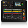
7 X32 COMPACT DIGITAL MIXER User Manual Ch01 FatSnare 01 OpeningScene 02: next home con g 0:00 gate - 0:00 dyn A: S16 B: - eq 15:33 A: 48K C: X-USB : 15 sends main Main Display Area The main color display presents information about various sections of the console. It can be switched to different screens using the console's View buttons, as well as any of the 8 buttons on the right side of the display. The top section of the main display permanently covers useful status information. The top left corner shows the selected channel number, its nickname and the selected icon. The next block shows the current scene number and name in amber, as well as the next upcoming scene. The center section displays the playback file name along with elapsed and remaining time and a recorder status icon. The next block to the right has 4 segments to show the status of AES50 ports A and B, the Card slot and the audio clock synchronization source and sample rate (top right). Small green square indicators show proper connectivity. The right most block shows the console time that can be set under Setup/Config. When working with any given screen, press the Page keys located on the display bezel to switch to different screen pages. Editing parameters or settings on each of the screens is done using the 6 associated push-encoders along the bottom edge of the display. • Whenever there is a continuous control or list entry, you can turn the corresponding knob for editing, which is indicated by various circular icons • When there is a switch or toggle function on one of these knobs, you will see a broad rectangular button along the lower edge of the field. Pressing the encoder changes the on/off state of the corresponding function. When the rectangular button in the display is dark grey, the corresponding function is off/inactive; when it is amber, the function is on/active Group/Bus Channel Banks This section of the console offers eight channel strips, divided into the following layers: • Eight DCA (digitally controlled amplifier) groups • Mix Bus masters 1-8 • Mix Bus masters 9-16 • Matrix Outputs 1-6, and the main center bus This section also contains a main LR output fader, which is independent and always available no matter which channel bank or layer is active. When using the DCA Groups layer, the DCA Groups can be soloed and muted, but they cannot be selected. To edit the DCA group names, icons and colors, navigate to the Setup/DCA Groups page on the main display. When using any of the output bus layers, note that the bottom LEDs on the meters in this section illuminate when the respective bus is fed from pre-fader sources of the selected channel. Various Assignments (DCA groups, mute groups, custom assignable controls) • Assigning DCA Groups Thanks to the two distinct fader groups (inputs on the left, outputs on the right), the task of assigning channels or buses to a virtual DCA Group is a breeze on the X32 COMPACT. Simply hold the respective DCA Group Select button on the righthand side of the console, while pressing the select buttons for all the input channels that you wish to assign to said DCA Group. You can also press the DCA Group Select button in order to check which channels are already assigned to it. The assigned channel Select buttons will light up. • Assigning Mute Groups The mute group assignment process is similar to the above, but is designed with an additional precaution in order to prevent accidental muting of channels during a show. To assign input/output channels to one of the six mute groups (controlled by the buttons located to the right of the Main LR fader) you need to first switch on the Mute Grp button next to the main display. While holding the desired Mute Group button, select the desired input and output channels, which will now be assigned to the Mute Group. When you are done with assignment, switch off Mute Grp at the display, and the 6 Mute Group buttons will work as intended. • Custom Assignable Controls: The Assign section of the console offers three banks of 8 buttons, allowing for freely customizable access to 24 random functions of the X32 COMPACT. To make a custom assignment: • Press the View button in the Assign section to edit the assignments • Select the set of controls you wish to edit (A, B or C) • Select the control 1-8 you wish to assign • Select the parameter you wish to control and assign the function Usually this is used to control a specific channel's parameter, like the lead vocalist's reverb on/off status. The Jump-to-Page control is a special target type that does not alter any audio parameter, but rather brings you directly to any specified display page.
-
 1
1 -
 2
2 -
 3
3 -
 4
4 -
 5
5 -
 6
6 -
 7
7 -
 8
8 -
 9
9 -
 10
10 -
 11
11 -
 12
12 -
13
-
14
-
15
-
16
-
17
-
18
-
19
-
20
-
21
-
22
-
23
-
24
-
25
-
26
-
27
-
28
-
29
-
30
-
31
-
32
-
33
-
34
-
35
-
36
-
37
-
38
-
39
-
40
-
41
-
42
-
43
-
44
-
45
-
46
-
47
-
48
-
49
-
50
-
51
-
52
-
53
-
54
-
55
-
56
-
57
-
58
-
59
-
60
-
61
-
62
-
63
-
64
-
65
-
66
-
67
-
68
-
69
-
70
-
71
-
72
-
73
-
74
 |
 |
