Behringer XENYX XL2400 Manual - Page 13
Stereo channels, Stereo channel FX/MON/AUX send paths
 |
View all Behringer XENYX XL2400 manuals
Add to My Manuals
Save this manual to your list of manuals |
Page 13 highlights
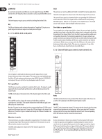
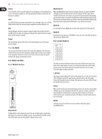
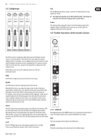
13 XENYX XL3200/XL2400/XL1600 User Manual CLIP The CLIP LED lights up as soon as the channel's level is too high. In this case, reduce the channel's input amplification with the TRIM control. 5.2.1 Equalizer stereo channels SIG The SIG LED lights up when a channel's signal is higher than -20 dB. The LED is not affected by the fader. The signals are indicated even when the fader is pulled down and the channel is muted. Fader The channel fader adjusts the level of the channel signal as part of the main mix (or submix). 1-2, 3-4, MIX The routing switch routes the signal to the respective subgroup or the main mix or both. The XENYX features 4 subgroups. The PAN control determines the group to which the signal is routed (fully left: Sub 1 or 3, fully right: Sub 2 or 4). 5.2 Stereo channels The stereo channels provide 4-band equalization. Each frequency band can be boosted and cut up to 15 dB and has a flat response when the controls are in center position. HIGH The HIGH control of the EQ section adjusts the high-frequency range of the respective channel. This is a shelving filter which boosts and cuts the frequencies above 12 kHz. HIGH MID The HIGH MID control adjusts the mid frequency range. This is a peak filter which boosts and cuts the frequencies centered at 3 kHz. +48 V This control LED lights up when the phantom power is activated. The switch is located on the rear panel of the unit. MIC TRIM The MIC TRIM control adjusts amplification of the microphone input. The amplification ranges between 0 and +60 dB. ◊ Be sure to set this control fully counter-clockwise before you connect or disconnect a signal source to or from one of the inputs. 80 Hz Press the 80 Hz switch to activate the high-pass filter which blends out low-frequency noise (-3 dB at 80 Hz, 18 dB/octave). LINE TRIM The LINE TRIM control adjusts the amplification of the LINE input, ranging between -20 and +20 dB. When centered (at 12 o'clock), the line signal is neither boosted nor cut. LOW MID The LOW MID control adjusts the mid frequency range. This is a peak filter which boosts and cuts the frequencies centered at 300 Hz. LOW The LOW control adjusts the low-frequency range. This is a shelving filter which boosts and cuts the frequencies below 80 Hz. EQ The EQ push-button switch activates the equalizer. Toggle the EQ to give you a quick comparison between unprocessed and processed signal. 5.2.2 Stereo channel FX/MON/AUX send paths The aux and FX paths of the stereo channels work in principle the same way as the mono channels. Since the aux buses are mono, the stereo signal needs to be converted to a mono signal before being routed to these buses. 5.2.3 Channel fader, pan control, mute switch, etc. BAL(ANCE) The BAL(ANCE) control has the same function as the PAN control on the mono channels. It determines the relative volume of the left and right input signals before they are routed to the stereo main mix bus (or to two subgroups). MUTE Use the MUTE switch to mute the channel signal. The MUTE LED is illuminated when the channel is muted
-
 1
1 -
2
-
3
-
4
-
5
-
6
-
7
-
 8
8 -
 9
9 -
 10
10 -
 11
11 -
 12
12 -
 13
13 -
 14
14 -
 15
15 -
 16
16 -
 17
17 -
 18
18 -
19
-
20
-
21
-
22
-
23
 |
 |
