Beko HNE51210 Owners Manual - Page 12
Installation, Electrical connection, Mounting
 |
View all Beko HNE51210 manuals
Add to My Manuals
Save this manual to your list of manuals |
Page 12 highlights
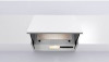
Installation The minimum distance between the supporting surface for the cooking equipment on the hob and the lowest part of the range hood must be not less than 50cm from electric cookers and 70cm from gas or mixed cookers. If the instructions for installation for the gas hob specify a greater distance, this must be adhered to. Electrical connection The mains power supply must correspond to the rating indicated on the plate situated inside the hood. If provided with a plug connect the hood to a socket in compliance with current regulations and positioned in an accessible area, after installation. If it not fitted with a plug (direct mains connection) or if the plug is not located in an accessible area, after installation, apply a double pole switch in accordance with standards which assures the complete disconnection of the mains under conditions relating to over-current category III, in accordance with installation instructions. Warning! Before re-connecting the hood circuit to the mains supply and checking the efficient function, always check that the mains cable is correctly assembled. Warning! Power cable replacement must be undertaken by the authorised service assistance centre or similar qualified person. Mounting Expansion wall plugs are provided to secure the hood to most types of walls/ceilings. However, a qualified technician must verify suitability of the materials in accordance with the type of wall/ceiling. The wall/ceiling must be strong enough to take the weight of the hood. Do not tile, grout or silicone this appliance to the wall. Surface mounting only. Before beginning installation: • Remove the fats filter/s or the suction grill/s (depending on the model in possession -see also the relative paragraph). This/these is/are to be mounted once installation is completed. • Remove the active carbon (*) filter/s if supplied (see also relative paragraph). This/these is/are to be mounted only if you want lo use the hood in the filtering version. • Check (for transport reasons) that there is no other supplied material inside the hood (e.g. packets with screws (*), guarantees (*), etc.), eventually removing them and keeping them. • In addition check whether near the installation area of the hood (in the area accessible also with the hood mounted) an electric socket is available and it is possible to connect a fumes discharge device to the outside (only suction version). • Choose the discharge outlet to use: Only filtering version: use ONLY the upper B1 outlet (Fig. 2 - Fig. 2.2). Check that this, once installation is completed, is not obstructed and that there is sufficient space so that the purified fumes and steam can return easily into the kitchen. Press with decision (Fig. 3.1) to take away the pre- fractured part (B1 o B2) that closes the discharge outlet and remove it. Install the connection ring on the open discharge outlet (Fig. 3.2 bayonet embedded) or the deflector (*). (Fig. 3.3). Check that the lateral wall units between which to install the hood are sufficiently robust for installing the hood. Otherwise mount the hooking brackets on the wall (*) to use as additional supports: a. Insert each bracket from the rear inside the hood through the apposite slots (Fig. 4.1-Fig. 4.2). b. Fix the brackets with the screws and threaded bushes (Fig. 4.3). Screw the headless screws halfway. They will serve to adjust the position of the hood at the moment of installation. Note: the position of the brackets can be adjusted during installation, suitably loosening and retightening the screws that fix them to the hood. (Fig. 7 - S1-S2). Installing the aesthetic panel (*) a. Extract the steam collector (freeing it from the blocking hooks - Fig. 5). b. Put perforation diagram N3 on the REAR of aesthetic panel J (the arrow on the diagram turned upward towards the UPPER EDGE of the aesthetic panel). Fig. 6 c. Make BLIND HOLES K as indicated. Fig. 6 d. Put the steam collector over the aesthetic panel and fix it with 8 screws L. Fig. 6 e. Remount the door on the hood, first on upper guides M1, then on the lower M2. Fig. 6 f. Close completely and re-open the door to check its correct sliding on the guides. Electrical or mechanical valve (*) Fig. 11 In some products an electrically or mechanically activated valve is envisaged instead of an aspiration motor. This is usually installed on discharge outlet B1 and fixed to the caisson of the hood with 3 screws, while a stopper is installed in outlet B2, fixed in its turn with 1 screw. If you want to install the valve on outlet B2, dismantle the valve from the caisson, remove the fixing screws, and install it in place of the stopper, the latter to be fixed on the cover of outlet B1. Installation a. Use perforation diagram N2 (*). Position the diagram on the front edges of the wall unit (right wall unit, B side) - (left wall unit, C side) WITHOUT CONSIDERING THE THICKNESS OF THE DOORS, and make the holes as indicated. Fig. 8 b. If necessary, fix the hood to the wall, putting template N1 (*) on the wall so its upper edge coincides with the upper edge of template N2 (*). Fig. 7-8 c. Make the holes as indicated. Fix 2 hooks (*) R to the wall with screws and dowels. Fig. 7 11
-
 1
1 -
2
-
3
-
4
-
5
-
6
-
 7
7 -
 8
8 -
 9
9 -
 10
10 -
 11
11 -
 12
12 -
 13
13 -
 14
14 -
 15
15 -
 16
16 -
 17
17 -
18
-
19
-
20
-
21
-
22
-
23
-
24
-
25
-
26
-
27
-
28
-
29
-
30
-
31
-
32
-
33
-
34
-
35
-
36
-
37
-
38
-
39
-
40
-
41
-
42
-
43
-
44
-
45
-
46
-
47
-
48
-
49
-
50
-
51
-
52
-
53
-
54
-
55
-
56
-
57
-
58
-
59
-
60
 |
 |
