Belkin F6C550-AVR User Manual - Page 1
Belkin F6C550-AVR Manual
 |
View all Belkin F6C550-AVR manuals
Add to My Manuals
Save this manual to your list of manuals |
Page 1 highlights
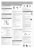
Battery Backup with Surge Protection User Manual F6BC95050-UAVNRV,, FF66CC795000--AUVNRV,,F6B750-AVR, F6C191000-U-UNNV,VF, 6F6CC112000-U-UNNV,VF6C1200-UNV Introduction Thank you for purchasing Battery Backup with Multi-Computer Connections (the Unit). Each year, frequent natural and man-made power disturbances disrupt the power supplied to your home or office electronics. These power problems place your hardware, software, and data at risk. Belkin Battery Backups provide an uninterruptible power supply (UPS) with advanced features as the industry-leading solution. Package Contents You should have received the following: 1 - Battery Backup unit 1 - Installation CD containing Belkin Automatic Power Management Software (the Belkin APM Software) for Windows® 1 - USB Cable 1 - Serial Cable(F6C900-UNV, F6C1100-UNV, F6C1200-UNV) 1 - Phone-Line Cable 1 - Coaxial-Cable(only F6B750-AVR) System Requirements The Unit can be used without the software and can be used with any computer using a monitor or a flat-panel screen. Also, you do not have to have the software installed to utilize the battery-backup outlets. To fully utilize the Battery Backup and its software, your computer must be able to run one of the following operating systems: Windows XP / 2003 / 2000 / ME / 98 / NT 4.0 (SP6) or Linux, and it must have a serial or USB port. Overview | Features and Functions Your Battery Backup features three LED indicators that monitor certain functions on the Unit. Please review the front-panel diagram and refer to this chart. This will assist you in the use of your Battery Backup. Indicator ON LINE (Green LED) ON BATTERY (Yellow LED) Condition ○ Solid Green * Flashing Green * Flashing Yellow LED with Audible Alarm (Beeping) Meaning AC power is on. AVR is active. This condition for the "ON BATTERY" LED can indicate 1 of 2 problems: 1. The Unit is in backup mode and an intermittent audible alarm is on. The Unit will begin shutdown procedure. 2. Battery is low. The Unit will start shutdown procedure. The buzzer sounds an audible alarm. FAULT OVERLOAD Replace Battery (Red LED) ○Solid Red The "FAULT/OVERLOAD" LED can indicate 1 of 2 problems. 1. There is a problem with the Unit. The LED will be lit continuously, and the Unit will sound an audible alarm for 10 seconds. 2. Battery is weak or bad; the battery needs to be replaced. * Flashing Red SITE WIRING FAULT (On Rear Panel) ○Solid Red Battery output is drawing more power than the Unit can provide. There is either no ground circuit or a reversed polarity in the building wiring. Overview | Alarms Battery Backup (Slow Alarm) When the Unit is in "backup" mode (running on battery), the YELLOW LED illuminates and the Unit emits an audible alarm. The alarm stops when the Unit returns to normal online operation. Low Battery (Rapid Alarm) In "backup" mode, when the battery energy runs low, the Unit beeps rapidly until it either shuts down from a depleted battery or returns to normal online operation. Overload (Continuous Alarm) When the Unit is overloaded (the connected loads exceed the maximum rated capacity), it emits a continuous alarm to warn of an overload condition. Disconnect nonessential equipment from the Unit to eliminate the overload. Fault (10 Seconds Continuously) When the Unit fails, it emits an audible alarm continuously for 10 seconds to warn of a fault condition. Disconnect the equipment prior to checking it. Overview | Top and Rear Panels Note: TOP PANEL REAR PANEL A. Surge-Protected-Only Outlets Equipment such as a printer, fax machine, scanner, or a desk lamp can be plugged into these outlets. These outlets do not provide battery power during a outage. They are always on (when AC power is available) and are not controlled by the front-panel switch. B. Battery-Backup Outlets Only data-sensitive equipment such as a computer, monitor, and external drive should be plugged into these outlets. Battery power is automatically provided in case of a power outage. Power (AC or battery) is not supplied to these outlets when the Unit is switched off. (Do not plug surge protectors or power strips into the battery-backup outlets.) Note! During the AVR Mode, the total load that you will be placing on the battery-backup outlets should not exceed 85% of the Unit's capacity. C. Phone/Fax/Modem Protection The phone/fax/modem lines are surge-protected and provide complete safety for line connection. D. Interface Ports (USB & RS232) The Unit provides a USB port for use with your computer. For the F6C900-UNV, F6C1100-UNV, F6C1200-UNV model, the unit provides both a USB and RS232 port. NOTE: Choose one port only. E. AC Input Breaker (Circuit Breaker) The circuit breaker button will be triggered if an overload condition forces the Unit to disconnect itself from utility power. If the button sticks out, disconnect nonessential equipment and depress breaker. F. AC Input Power Cord G. Site Wiring Fault Indicator The "SITE WIRING FAULT" LED will illuminate when one of the following conditions exist: 1. Open or high-resistance ground 2. Hot and neutral polarity reversal 3. Overloaded neutral circuit H. Audio Video Surge-Protection Port (Only F6B750-AVR) I. Network Protection(F6C900-UNV/F6C1100-UNV/F6C1200-UNV) This connector is used for protecting the transmission line of an Ethernet card from surges, noise, and spikes. Model F6C550 F6C750 -AVR -AVR F6B750 F6C900 F6C1100 F6C1200 -AVR -UNV -UNV -UNV Input Capacity 550VA/ 330W 750VA/ 400W 900VA/ 1100VA/ 1200VA/ 540W 660W 670W Voltage Range 89-145VAC Frequency 60Hz (±5Hz) Output Voltage Frequency (On Battery) Simulated sine wave, 120VAC ±15% 60Hz (±1Hz) Battery Backup Time Half-Load 8 min. 5 min. 6 min. 4 min. Typical Recharge Time 16 hours recover to 90% capacity Environment Ambient Operation Conformance Safety Physical Surge Dimensions (W x H x D) 0~90% humidity non-condensing, 0~40º C UL / c-UL, FCC Class B IEEE C62.41 Category A standard 294.5 X 125 X 242.5 mm. Net Weight 5.9kg. 6.25kg. All specifications are subject to change without prior notice. 9.25kg . Overview Storage Storage Conditions Store the Unit covered and upright in a cool, dry location with its battery fully charged. Before storing, charge the Unit for at least four (4) hours. Disconnect any cables connected to the computer interface port to avoid unnecessary drainage of the battery. Extended Storage During extended storage in environments where the ambient temperature is +5º F to +86º F, charge the Unit's battery every six (6) months. During extended storage in environments where the ambient temperature is +86º F to +113º F, charge the Unit's battery every three (3) months. Please save this User Manual! It contains important operating instructions and warranty information pertaining to your Battery Backup. Please save or recycle the packaging materials! The Unit's packaging was designed with great care to provide protection during shipment and delivery. These materials are invaluable if you ever have to return the Unit for service. Damage sustained during transit is not covered under the warranty. Installation Note! Before installation, please inspect the Unit. Make sure that nothing inside the package is damaged. Connect to AC Utility Power Plug in the AC cord to a wall outlet. Please make sure there are no devices plugged into the Unit. Check to see whether the "SITE WIRING FAULT" indicator is lit. If it is lit, have the utility wiring inspected by an electrician. Charging the Battery For best results, charge the battery for eight hours prior to initial use. The Unit charges its battery whenever it is connected to the utility power. Plug in Power Devices Plug your devices into the AC outlets on the top of the Unit. To use the Unit as a master on/off switch, make sure all of the loads are switched on. Caution: Never connect a laser printer or scanner to the backup outlets along with other computer equipment. A laser printer or scanner draws significantly more power when in use than when idle. This may overload the Battery Backup. Turning on the Unit Turn on your Battery Backup by pressing and holding the "ON/OFF/TEST" button for approximately two seconds until the "ON LINE" green light comes on. Turning off the Unit Turn off the Unit by pressing and holding the "ON/OFF/TEST" button for more than two seconds until the "ON LINE" or "ON BATTERY" LED goes off. To Conduct a Self-Test Use the self-test to verify both the operation of the Unit and the condition of the battery. In normal utility power, push the "ON/OFF/TEST" button less than 1.5 seconds and the Unit performs a self-test function. During the self-test, the Unit operates in backup mode. Note: During the self-test, the Unit briefly operates on battery-backup power (the "ON BATTERY" LED comes on). If the Unit passes the self-test, it returns to online operation. If the Unit fails the self-test, it immediately returns to online operation and lights the "Replace Battery" LED. The loads are not affected. Recharge the battery overnight and perform the self-test again. If the "Replace Battery" LED is still on, the battery needs to be replaced. To Silence Audible Alarm While the Unit is in battery-backup mode, push the "ON/OFF/TEST" button for less than 1.5 seconds to silence the audible alarm. (This does not work if the Unit is in a OVERLOAD condition.) All equipment must be powered off prior to plugging into the Unit (installation). Connect the Phone/Fax/Modem Lines Connect a single phone/fax/modem line into the surge-protected outlets on the back of the Unit. The RJ11 modular outlet accepts standard single-line telephone connections. The connection will require another length of telephone cable (included). NOTE: This connection is optional but highly recommended as phone/ fax/modem lines often carry dangerous surges and spikes. The Unit works properly without a phone/fax/modem connection. Caution! The phone/fax/modem protection feature could be rendered inoperable if improperly installed. Make sure that the telephone line from the wall is plugged into the connector marked "IN", and the device to be protected is plugged into the connector marked "OUT". Battery Replacement Procedure Replacement requires removing the battery cover plate on the back or bottom of the Unit. No tools are needed. To replace the batteries: 1. Press fastener to remove the battery cover plate on the back of the Unit (Fig. 1). 2. Disconnect the insulated connectors from the battery terminals (Fig. 2). 3. Remove the battery, insert a new battery pack, and push the connectors onto the battery terminals (black-to-black and red-to-red) (Fig. 3). NOTE: There may be a small spark at the battery terminals when reconnecting the connectors. This is normal and will not harm you or the Unit. 4. Close the battery cover (Fig. 1). Fig.1 Fig.2 Fig.3
-
 1
1 -
 2
2
 |
 |