Belkin F6H500-SER User Manual - Page 1
Belkin F6H500-SER Manual
 |
View all Belkin F6H500-SER manuals
Add to My Manuals
Save this manual to your list of manuals |
Page 1 highlights
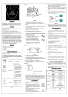
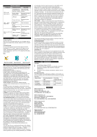
○R F6H350-SER F6H500-SER F6H650-SER F6H500-USB Front Panel 2 3. Turn off the UPS before installing any products into the UPS or Surge outlets. Please be sure all equipment to be installed into any of the outlets is turned off. This will ensure that a power disturbance will not affect your equipment. 4. Plug in only one computer and monitor into the UPS outlets. We strongly recommend that only this equipment be plugged into the UPS outlets. For all other equipment, plug into the Surge outlets. 5. Plug one end of the phone cable you received into your telephone jack and plug the other end into the jack marked IN. You may now plug a phone, fax or modem into the two jacks marked OUT. (See Diagram 3) 3 Phone 1 INTRODUCTION Thank you for purchasing a Belkin Uninterruptible Power Supply (UPS). Each year, several natural and man made occurrences put the power supplied to your work stations in your home or office in jeopardy. At risk is your hardware, software and data because of these power problems. IMPORTANT! Please save this manual! It contains important operating instructions and warranty information pertaining to your UPS. Please save or recycle the packaging materials! The UPS packaging was designed to provide protection during shipment and delivery. This packaging can be reused should you have return the UPS for service. Damage sustained during transit is not covered under the warranty. Federal Communications Commission Interference Statement This equipment has been tested and found to comply with the limits for a Class B digital device, pursuant to Part 15 of the FCC Rules. These limits are designed to provide reasonable protection against harmful interference in a residential installation. This equipment generates, uses and can radiate radio frequency energy and, if not installed and used in accordance with the instructions, may cause harmful interference to radio communications. To assure continued compliance, use only shielded interface cables when connecting to computer or peripheral devices. Any changes or modifications not expressly approved by the party responsible for compliance could void the user's authority to operate this equipment. CONTENTS You should have received the following: 1 - UPS unit 1 - Sentry Bulldog Shutdown Software 1 - Serial Cable 1 - USB Cable 1 - Phone Line Cable UPS FEATURES AND FUNCTIONS Before installation, please inspect the UPS upon receipt. Make sure that nothing is damaged. Your UPS features 3 LED indicators. Each is marked by a power icon, please familiarize yourself with this chart as it will assist you in the use of your UPS. Indicator LED Indication Description ON-LINE О Solid green AC power is on ON-BATTERY and LOW-BATTERY ☼ Flashing Red The On-Battery and Low-Battery LED can indicate 1 of 3 conditions: 1. The UPS is on battery backup if the green light is off and an intermittent audible alarm is on. The UPS will begin shutdown procedure. 2. Battery is low. The UPS will start shutdown. The buzzer sounds an audible alarm. 3. There is a problem with the UPS. The LED will be lit continuously and the buzzer will sound audible alarm for 10 sec. SITE WIRING FAULT О Solid Red The Site Wiring fault LED can indicate 1 of 2 possible conditions: 1. Open or high resistance ground 2. Hot or neutral polarity circuit Chart 1 Diagram 1 1. UPS Outlets (See #1 on Diagram 1) These outlets are your battery back up outlets. We strongly recommend that only sensitive equipment such as your computer and monitor should be plugged into these outlets. Never plug in any printer. Should a power outage occur, your battery backup will automatically turn on. Power (utility or battery) is not supplied to these outlets when the UPS is switched off. Please do not plug any surge protectors or power strips into the battery back-up outlets (i.e. daisy chaining). To Telephone Socket Modem / Fax Diagram 4 6. (Optional) To full utilize the Sentry Bulldog Shutdown Software, you will need to connect the UPS to your computer. Connect the RJ45 jack to your UPS then connect the serial end to the serial port on your computer. SOFTWARE INSTALLATION (Optional) 2. SURGE Protected outlets (See #2 on Diagram 1) These outlets do not provide power during a power outage. Equipment such as computer peripherals, printers, fax machine's, or a desk lamp may be plugged into these outlets. These outlets are not controlled by the On/Off button. 3. The On/Off button has 3 functions: 1. Turns on the UPS. Depress button at least 2 seconds. The green light will come on. 2. Cold Start function. Assuming the battery is charged the UPS will work without it being plugged into an outlet. Depress and hold the key for at least 2 seconds to turn on the UPS. The 3. Silence function. During "On Battery Mode", the audible sound can be turned "ON" or "OFF" by depressing the switch. 1. Your UPS features the Sentry Bulldog Shutdown Software. This allows protects and saves your data should a power outage occur. 2. To install the software, please place the CD into the CD player of your computer. 3. Your computer should automatically run the CD. If this does not occur, goto the Run feature on your Start icon (lower left corner) on your screen. Please enter the CD drive, it may be D:. Should you continue to have a problem, please refer to your computer's owner's manual for the correct drive. 4. Once uploaded, please click the Bulldog icon on the screen. 5. Click Install Belkin Sentry Bulldog for Win 95/98/ME/NT4/2000/XP 6. InstallShield Wizard will appear onscreen, click Next. Side Panel A 3 Circuit Breaker Push to Reset Refer to Bottom for Cautionary Markings AC Input OUT Phone/Fax Modem OUT Protection IN 1 2 7. Please read the License Agreement and click Yes. 8. On Setup Type, click ALL (Standalone). You should not install the networking files unless you technically qualified to use these features. 9. On Choose Destination, click Next. 10. On Select Program Folder, click Next 11. On Setup Type, please choose your language choice. Diagram 2 4. AC Input Power Cord (See #1 on Diagram 2) Provides power to your UPS. 12. The software will now upload. Once completed, please click Finish. 13. Please click the appropriate user's manual to download. 5. Phone/ Fax/ Modem Surge Protection (See #2 on Diagram 2) The Phone/ Fax/Modem lines are surge protected. There is one input jack and two output jacks. 6. AC Breaker (Circuit Breaker; See #3 on Diagram 2) Should a power overload occur, the circuit breaker will trigger the UPS to turn off AC power. Side Panel B 14. Click X on the Bulldog setup screen to leave the software setup. 15. Please refer to the user's manual for software setup and information on software features. Uninstall for Windows 95/98/Me/NT4/2000/XP There are two options to uninstall the Sentry Belkin Shutdown Software. 1. Select the Setup from the BELKIN SENTRY BULLDOG program folder and select the remove option to begin the uninstall procedure. 2. Select Add/Remove Programs from the Control Panel and click on the BELKIN SENTRY BULLDOG item then press the Add/Remove button. TECHNICAL SPECIFICATIONS Serial Communication Port Diagram 3 7. Your UPS features a serial communication port. Installation of the cable and software is optional. This allows the UPS to connect to you computer. The Sentry Bulldog Software will not work if the UPS is not connected to you computer. This does not mean the battery backup feature will not work without the software and cable installed. The UPS will still provide backup power but you will be unable to utilize the data management capabilities of the software. UPS INSTALLATION 1. Please plug in your UPS without any equipment plugged in. 2. Turn on your UPS by depressing the On/Off button for approximately 2 seconds. You will see the green indicator light come on. We recommend you charge the battery for at least 8 hours prior to full use. The battery will not charge unless the UPS is turned on. Should you see the red battery light come on, the battery may need charging. Battery Light MODEL INPUT RATED CAPACITY RATED VOLTAGE PHASE / FREQUENCY OUTPUT VOLTAGE FREQUENCY BATTERY BACK UP TIME RECHARGE TIME ENVIRONMEN TEMPERATU RE T HUMIDITY SAFETY REGULATION SAFETY EMI EMS F6H500-USB 500VA /300W 105-135Vac Single phase 60HZ Step wave 60HZ (±1HZ) Desktop computer +17" monitor≧ 13mm ≦ 8hours to 90% 0~35℃ 10~90% UL1778 / C-UL FCC CLASS B IEEE C62.41 CATEGORY A DIMENSION APPEARANCE NET WEIGHT 3.14 X 9.84 X 6.6 inches 140..61K4GLBSS/ Should the red site wiring fault light come on. Please refer to the UPS Features and Functions (Chart 1) for the proper reference. All specifications are subject to change without prior notice. Site Wiring Light
-
 1
1 -
 2
2
 |
 |