Beltronics Sti-R Installation Manual - Page 2
STi-R Installation Manual - radar
 |
UPC - 065789270709
View all Beltronics Sti-R manuals
Add to My Manuals
Save this manual to your list of manuals |
Page 2 highlights
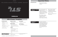
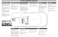
STi-R Installation Manual A Radar/Laser Receiver B Radar/Laser Receiver Cable 1 Determine the best location for the Receiver. The best location is typically under the bumper, or inside the front grill of the vehicle. For the best performance, install the Receiver horizontally, with a clear "view" of the road. 2 Using the supplied mounting hardware, mark the hole locations and drill pilot holes in the vehicle if necessary. It's best to check and double-check clearances BEFORE drilling the holes. 1 Connect the receiver cable to the Receiver. 2 Route cable to firewall, and secure with zip-ties (included). 3 Route receiver cable into the vehicle's interior. If there is not a suitable opening, drill a 13/32" or 7/16" hole. 4 Pull cable through firewall, and plug connector into the jack labeled "Front Receiver" on the Interface. 3 Mount the Receiver using the supplied hardware. (If right-angle mounting bracket is used, secure Receiver to the right-angle bracket first, then install bracket with Receiver to the vehicle.) 5 Pull grommet (located on the receiver cable itself) through the firewall to seal the hole. Use silicone sealant (not supplied) if necessary. Note: 1. Connection between the Receiver and the receiver cable, must be located in a dry location under the hood. 2. Only drill hole in firewall after thoroughly investigating location first, ensuring no other wires, hoses, etc. will be damaged. 3. Keep all cables away from moving parts, and hot surfaces (radiator, hoses, etc.). 4. DO NOT splice cable. D Optional Concealed Display E Display F Controller 1 Drill a 1/4" hole, and install the LED clip. 2 Snap LED into clip from behind. 1 Determine the best location for the Display in the vehicle's interior. (Consult customer if necessary.) 1 Determine the best location for the Display Controller in the vehicle's interior. (Consult customer if necessary.) 3 Plug the modular connector into STi-R's Interface marked "Concealed LED Display." 2 Install Display using double-sided tape on the back. Simply remove paper backing and press onto clean surface. You may also custom-install the display into the dashboard using the supplied template. Seek professional assistance for this. 3 Route cable and plug into jack marked "Display" on Interface. Note: Make certain that the Display is clearly visible from the driver's position. 2 Install Controller using supplied doublesided tape located on the back. Simply peal off the paper backing and press onto clean surface. 3 Route cable and plug into jack marked "Controller" on the Interface. Note: Make certain that the Controller can be easily accessed without interfering with normal driving. Note: 1. Do not drill holes in the Receiver itself. 2. Thoroughly investigate location before drilling any holes. 3. Keep all cables away from moving parts, and hot surfaces (radiator, hoses, etc.). 4. DO NOT splice cable. A B 12 Volt ± Power Line D E Interior of Vehicle C F A G C Interface 1 Install Interface under the dash using supplied zip-ties. DO NOT MOUNT IN ENGINE COMPARTMENT. 2 Connect black wire (-) to ground, and redstriped wire (+) to a switched 12-volt supply. (If STi-R is left in the "on" position, it will automatically power on and off with the ignition). Use blue 3M connector (provided) to tap into existing circuit if needed. 3 The front Receiver, Display and Controller all plug into the Interface. (Be sure to plug all cables into the correct labeled jacks.) G Amplified Speaker 1 Determine the best location for the Speaker in the vehicle's interior. (Consult customer if necessary.) Note: The speaker is loud enough to be mounted under the dash so it is not seen. 2 Mount the Speaker bracket using the supplies hardware. 3 Plug the audio line (ear phone jack connector) into the Interface jack marked "Speaker". 4 Connect the (+) to a switched power connection on the fuse panel, and connect the (-) to ground. TEST After all components are installed correctly: 1 Turn vehicle's ignition to the "on" position. 2 Turn the STi-R on by pressing the "PWR" button on the Controller. 3 The STi-R will cycle through a startup sequence. 4 If any error messages come up, see page 23 of the Owner's Manual for details.
-
 1
1 -
 2
2
 |
 |