Biostar 945GC-M7TE Setup Manual - Page 19
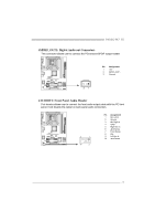
DVIJ1: Connector for DVI Daughter Card Adapter Optional, JUSBV1/JUSBV2: Power Source Headers for USB
 |
View all Biostar 945GC-M7TE manuals
Add to My Manuals
Save this manual to your list of manuals |
Page 19 highlights
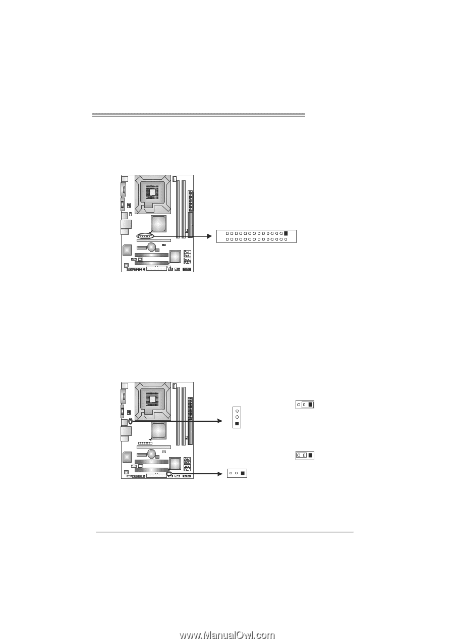
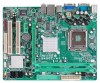
945GC-M7 TE DVIJ1: Connector for DVI Daughter Card Adapter (Optional) This connector is for the specific DVI adapter, which is equipped with a DVI-D connector. With the adapter you can use the DVI-D interface for a better display quality. Moreover, the original D-SUB and the additional DVI-D can be utilized simultaneously, so two panels can disaply simultaneously. 27 1 28 2 JUSBV1/JUSBV2: Power Source Headers for USB Ports Pin 1-2 Close: JUSBV1: +5V for USB ports at JRJ45USB1/JUSB2. JUSBV2: +5V for USB ports at front panel (JUSB3/JUSB4). Pin 2-3 Close: JUSBV1: USB ports at JRJ45USB1/JUSB2 are powered by +5V standby voltage. JUSBV2: USB ports at front panel (JUSB3/JUSB4) are powered by +5V standby voltage. JUSBV1 3 1 3 1 Pin 1-2 close JUSBV2 31 3 1 Pin 2-3 close Note: In order to support this function "Power-On system via USB device," "JUSBV1/ JUSBV2" jumper cap should be placed on Pin 2-3 individually. 17
-
 1
1 -
2
-
3
-
4
-
5
-
6
-
7
-
8
-
9
-
10
-
11
-
12
-
13
-
 14
14 -
 15
15 -
 16
16 -
 17
17 -
 18
18 -
 19
19 -
 20
20 -
 21
21 -
 22
22 -
 23
23 -
 24
24 -
25
-
26
-
27
-
28
-
29
-
30
-
31
-
32
-
33
-
34
-
35
-
36
-
37
-
38
-
39
-
40
-
41
-
42
-
43
-
44
-
45
-
46
-
47
-
48
-
49
 |
 |