Biostar G41U3G Setup Manual - Page 18
F_AUDIO1: Front Panel Audio Header, J_COM1: Serial port Connector
 |
View all Biostar G41U3G manuals
Add to My Manuals
Save this manual to your list of manuals |
Page 18 highlights
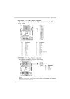
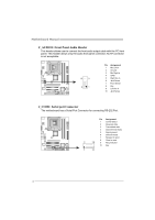
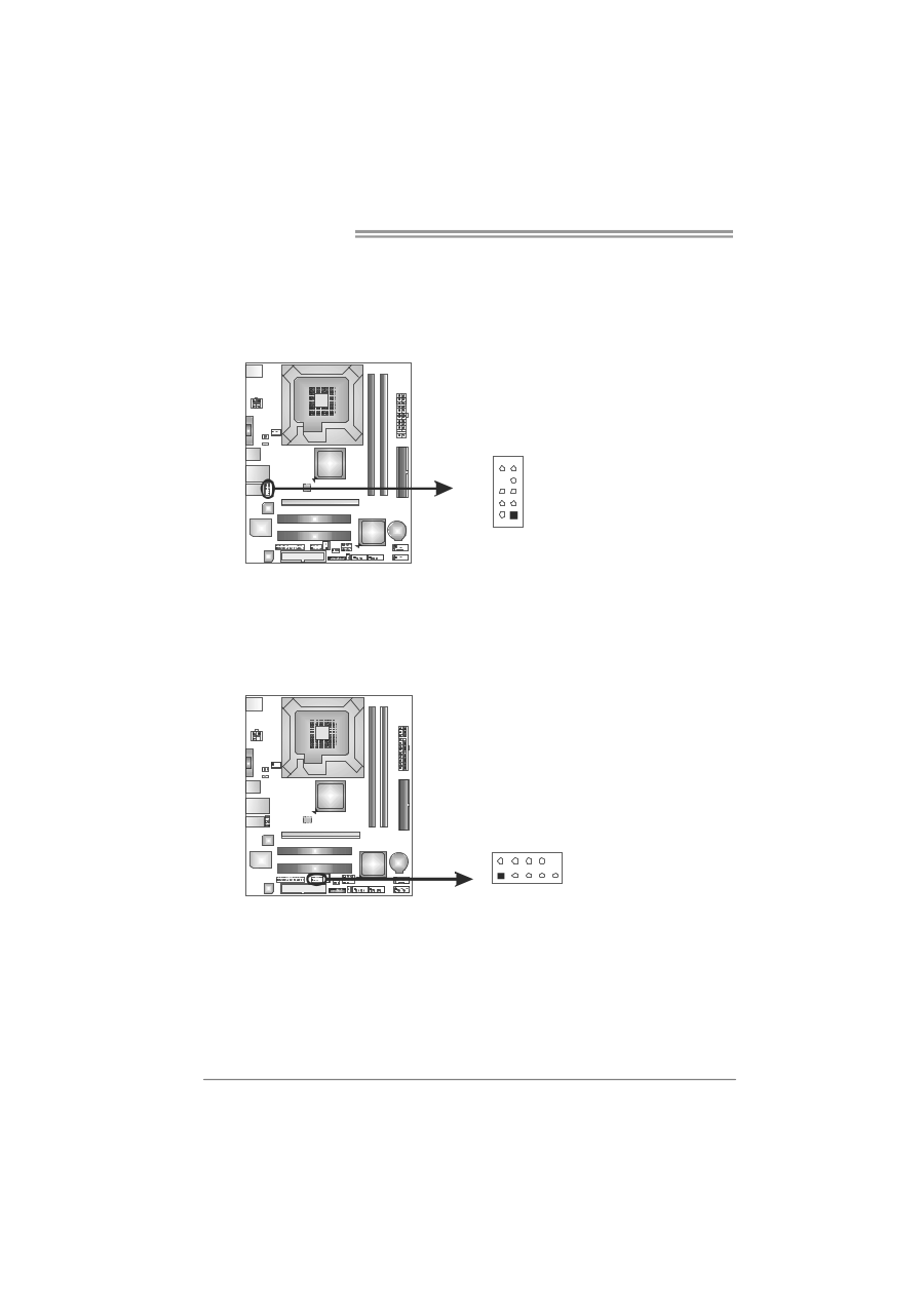
Motherboard Manual F_AUDIO1: Front Panel Audio Header This header allows user to connect the front audio output cable with the PC front panel. This header allows only HD audio front panel connector; AC'97 connector is not acceptable. 10 9 2 1 Pin Assignment 1 Mic Left in 2 Ground 3 Mic Right in 4 GPIO 5 Right line in 6 Jack Sense 7 Front Sense 8 Key 9 Left line in 10 Jack Sense J_COM1: Serial port Connector The motherboard has a Serial Port Connector for connecting RS-232 Port. Pin Assignment 1 Carrier detect 2 Received data 3 Transmitted data 4 Data terminal ready 5 Signal ground 6 Data set ready 7 Request to send 8 Clear to send 2 10 9 Ring indicator 10 Key 1 9 16
-
 1
1 -
2
-
3
-
4
-
5
-
6
-
7
-
8
-
9
-
10
-
11
-
12
-
 13
13 -
 14
14 -
 15
15 -
 16
16 -
 17
17 -
 18
18 -
 19
19 -
 20
20 -
 21
21 -
 22
22 -
 23
23 -
24
-
25
-
26
-
27
-
28
-
29
-
30
-
31
-
32
-
33
-
34
-
35
-
36
-
37
-
38
-
39
-
40
-
41
-
42
-
43
-
44
-
45
-
46
-
47
 |
 |
Motherboard Manual
16
F_AUDIO1: Front Panel Audio Header
This header allows user to connect the front audio output cable with the PC front
panel. This header allows only HD audio front panel connector; AC’97 connector
is not acceptable.
Pin
Assignment
1
Mic Left in
2
Ground
3
Mic Right in
4
GPIO
5
Right line in
6
Jack Sense
7
Front Sense
8
Key
9
Left line in
10
Jack Sense
1
9
2
10
J_COM1: Serial port Connector
The motherboard has a Serial Port Connector for connecting RS-232 Port.
Pin
Assignment
1
Carrier detect
2
Received data
3
Transmitted data
4
Data terminal ready
5
Signal ground
6
Data set ready
7
Request to send
8
Clear to send
9
Ring indicator
10
Key
1
2
9
10