Biostar GEFORCE 6100-M7 GeForce 6100-M7 user's manual - Page 17
JPANEL1: Front Panel Header
 |
View all Biostar GEFORCE 6100-M7 manuals
Add to My Manuals
Save this manual to your list of manuals |
Page 17 highlights
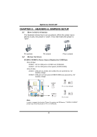
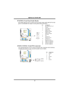
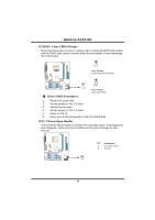
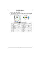
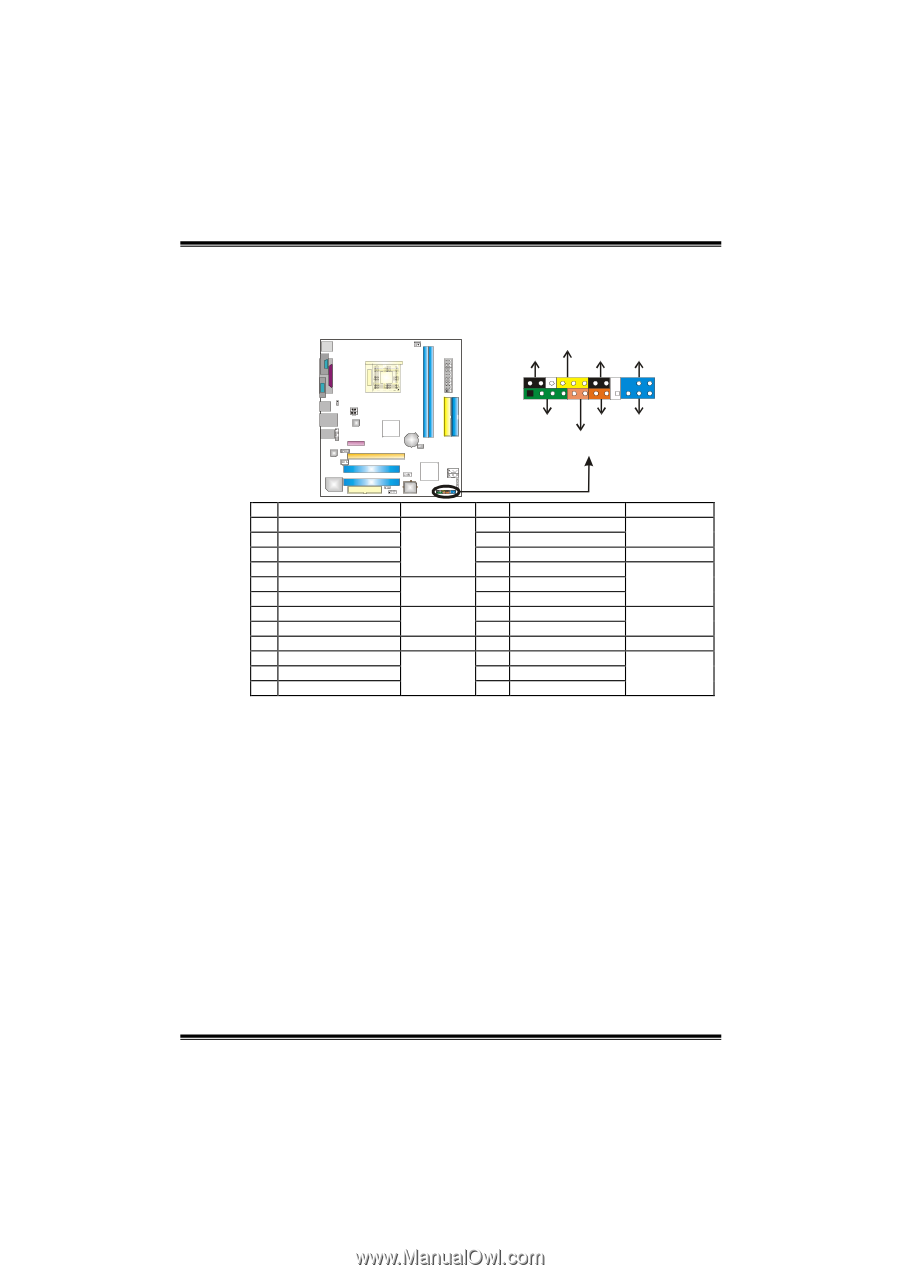
GeForce 6100-M7 JPANEL1: Front Panel Header This 24-pin connector includes Power-on, Reset, HDD LED, Power LED, Sleep button, speaker and IrDA Connection. It allows user to connect the PC case's front panel switch functions. PWR_LED SLP On/Off ++2 1 +- IR 24 23 SPK RST IR HLED Pin Assignment 1 +5V 3 N/A 5 N/A 7 Speaker 9 HDD LED (+) 11 HDD LED (-) 13 Ground 15 Reset control 17 N/A 19 N/A 21 +5V 23 IRTX Function Pin Assignment 2 Sleep control Speaker Connector 4 Ground 6 N/A 8 Power LED (+) Hard drive LED 10 Power LED (+) 12 Power LED (-) Reset button 14 Power button 16 Ground 18 Key IrDA Connector 20 Key 22 Ground 24 IRRX Function Sleep button N/A Power LED Power-on button IrDA Connector 15
-
 1
1 -
2
-
3
-
4
-
5
-
6
-
7
-
8
-
9
-
10
-
11
-
 12
12 -
 13
13 -
 14
14 -
 15
15 -
 16
16 -
 17
17 -
 18
18 -
 19
19 -
 20
20 -
 21
21 -
 22
22 -
23
-
24
-
25
-
26
-
27
-
28
-
29
 |
 |
GeForce 6100-M7
15
JPANEL1: Front Panel Header
This 24-pin connector includes Power-on, Reset, HDD LED, Power LED, Sleep
button, speaker and IrDA Connection. It allows user to connect the PC case’s
front panel switch functions.
1
23
24
SLP
PWR_LED
On/Off
IR
IR
RST
HLED
SPK
++
+
2
-
-
Pin
Assignment
Function
Pin
Assignment
Function
1
+5V
2
Sleep control
3
N/A
4
Ground
Sleep button
5
N/A
6
N/A
N/A
7
Speaker
Speaker
Connector
8
Power LED (+)
9
HDD LED (+)
10
Power LED (+)
11
HDD LED (-)
Hard drive
LED
12
Power LED (-)
Power LED
13
Ground
14
Power button
15
Reset control
Reset button
16
Ground
Power-on button
17
N/A
18
Key
19
N/A
20
Key
21
+5V
22
Ground
23
IRTX
IrDA
Connector
24
IRRX
IrDA Connector