Biostar GF7100P-M7S Setup Manual - Page 20
JUSBV1/JUSBV2: Power Source Headers for USB Ports
 |
View all Biostar GF7100P-M7S manuals
Add to My Manuals
Save this manual to your list of manuals |
Page 20 highlights
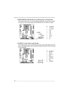
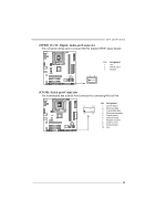
Motherboard Manual JUSBV1/JUSBV2: Powe r Source Heade rs for USB Ports Pin 1-2 Close: JUSBV1: +5V for USB ports at JUSBKB1/JUSBLAN1. JUSBV2: +5V for USB ports at JUSB2/JUSB3/JUSB4. Pin 2-3 Close: JUSBV1: USB ports at JUSBKB1/JUSBLAN1 are powered by +5V standby v oltage. JUSBV2: USB ports at JUSB2/JUSB3/JUSB4 are powered by +5V standby v oltage. 3 1 JUSBV1 3 1 Pin 1-2 close JUSBV2 13 3 1 Pin 2-3 close Note: In order to support this func tion "Power-On s ys tem via U SB device," "JUSBV1/ JUSBV2" jumper cap should be plac ed on Pin 2-3 indi viduall y. 20
-
 1
1 -
2
-
3
-
4
-
5
-
6
-
7
-
8
-
9
-
10
-
11
-
12
-
13
-
14
-
 15
15 -
 16
16 -
 17
17 -
 18
18 -
 19
19 -
 20
20 -
 21
21 -
 22
22 -
 23
23 -
 24
24 -
 25
25 -
26
-
27
-
28
-
29
-
30
-
31
-
32
-
33
-
34
-
35
-
36
-
37
-
38
-
39
-
40
-
41
-
42
-
43
-
44
-
45
 |
 |

Motherboard Manual
20
JUSBV1/JUSBV2: Power Source Headers for USB Ports
Pin 1-2 Close:
JUSBV1: +5V for USB ports at JUSBKB1/JUSBLAN1.
JUSBV2: +5V for USB ports at JUSB2/JUSB3/JUSB4.
Pin 2-3 Close:
JUSBV1: USB ports at JUSBKB1/JUSBLAN1 are powered by +5V standby
v oltage.
JUSBV2: USB ports at JUSB2/JUSB3/JUSB4 are powered by +5V standby
v oltage.
1
3
Pin 1-2 close
1
3
1
3
JUSBV1
JUSBV2
1
3
Pin 2-3 close
Note:
In order to support this func tion “Power-On s ys tem via U SB device,” “JUSBV1/ JUSBV2”
jumper cap should be plac ed on Pin 2-3 indi viduall y.