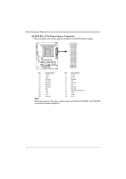
Biostar H61ML Setup Manual - Page 17
F_USB1/F_USB2: Headers for USB 2.0 Ports at Front Panel, JCMOS1: Clear CMOS Header, Clear CMOS - bios
 |
View all Biostar H61ML manuals
Add to My Manuals
Save this manual to your list of manuals |
Page 17 highlights
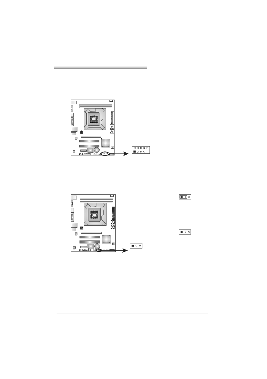
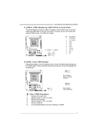
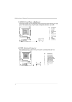
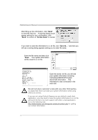
H61MGB/H61MLB/H61MHB F_USB1/F_USB2: Headers for USB 2.0 Ports at Front Panel This motherboard provides 2 USB 2.0 headers, which allows user to connect additional USB cable on the PC front panel, and also can be connected with internal USB devices, like USB card reader. F_ USB1 F_ USB2 2 10 1 9 Pin Assignment 1 +5V (fused) 2 +5V (fused) 3 USB4 USB5 USB+ 6 USB+ 7 Ground 8 Ground 9 Key 10 NC JCMOS1: Clear CMOS Header Placing the jumper on pin2-3 allows user to restore the BIOS safe setting and the CMOS data. Please carefully follow the procedures to avoid damaging the motherboard. 1 3 Pin 1-2 Close: Normal Operation (Default). 13 1 3 Pin 2-3 Close: Clear CMOS data. ※ Clear CMOS Procedures: 1. Remove AC power line. 2. Set the jumper to "Pin 2-3 close". 3. Wait for five seconds. 4. Set the jumper to "Pin 1-2 close". 5. Power on the AC. 6. Load Optimal Defaults and save settings in CMOS. 15
-
 1
1 -
2
-
3
-
4
-
5
-
6
-
7
-
8
-
9
-
10
-
11
-
 12
12 -
 13
13 -
 14
14 -
 15
15 -
 16
16 -
 17
17 -
 18
18 -
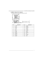 19
19 -
 20
20 -
 21
21 -
 22
22 -
23
-
24
-
25
-
26
-
27
-
28
-
29
-
30
-
31
-
32
-
33
-
34
-
35
-
36
-
37
-
38
-
39
-
40
-
41
-
42
-
43
-
44
-
45
-
46
 |
 |