Biostar I945G-M7 v1.x I945G-M7 user's manual - Page 17
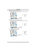
JPANEL1: Front Panel Header, JCI1: Chassis Open Header
 |
View all Biostar I945G-M7 v1.x manuals
Add to My Manuals
Save this manual to your list of manuals |
Page 17 highlights
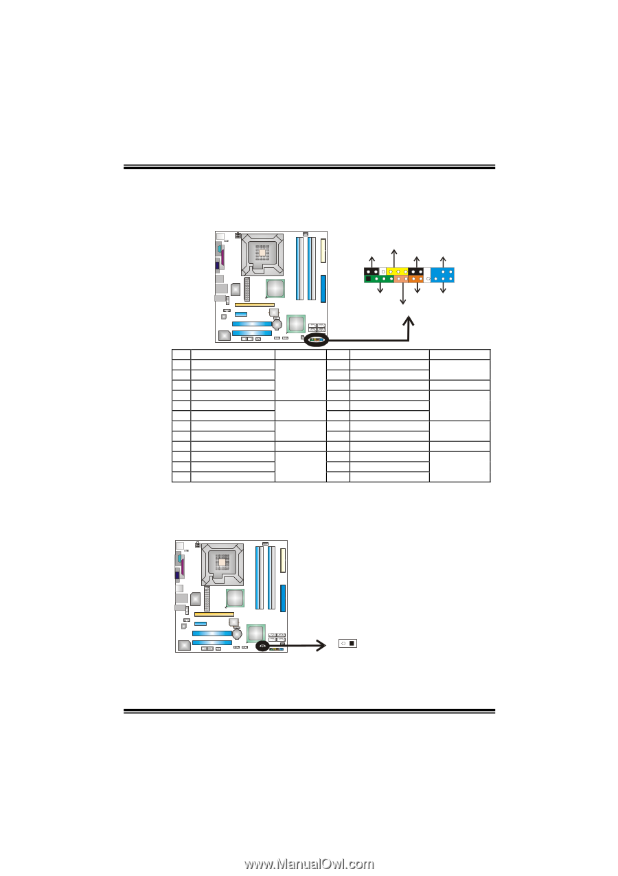
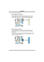
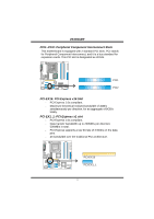
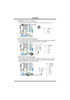
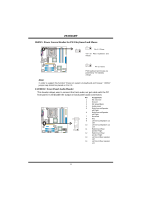
I945G-M7 JPANEL1: Front Panel Header This 24-pin connector includes Power-on, Reset, HDD LED, Power LED, Sleep button, speaker and IrDA Connection. It allows user to connect the PC case's front panel switch functions. COM1 PWR_LED SLP On/Off ++ 2 1 +- SPK RST HLED IR 24 23 IR Pin Assignment 1 +5V 3 N/A 5 N/A 7 Speaker 9 HDD LED (+) 11 HDD LED (-) 13 Ground 15 Reset control 17 N/A 19 N/A 21 +5V 23 IRTX Function Pin Assignment 2 Sleep control Speaker Connector 4 Ground 6 N/A 8 Power LED (+) Hard drive LED 10 Power LED (+) 12 Power LED (-) Reset button 14 Power button 16 Ground 18 Key IrDA Connector 20 Key 22 Ground 24 IRRX Function Sleep button N/A Power LED Power-on button IrDA Connector JCI1: Chassis Open Header This connector allows system to monitor PC case open status. If the signal has been triggered, it will record to the CMOS and show the message on next boot-up. COM1 Pin Assignment 1 Case open signal 2 Ground 21 15
-
 1
1 -
2
-
3
-
4
-
5
-
6
-
7
-
8
-
9
-
10
-
11
-
 12
12 -
 13
13 -
 14
14 -
 15
15 -
 16
16 -
 17
17 -
 18
18 -
 19
19 -
 20
20 -
 21
21 -
 22
22 -
23
-
24
-
25
-
26
-
27
-
28
-
29
-
30
-
31
 |
 |