Biostar K8T80-A7 User Guide - Page 10
CPU FAN Header: JCFAN1, System Fan Header: JSFAN1
 |
View all Biostar K8T80-A7 manuals
Add to My Manuals
Save this manual to your list of manuals |
Page 10 highlights
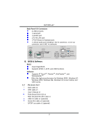
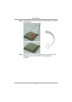
K8T80-A7 2.2 FAN HEADERS These fan headers support cooling-fans built in the computer. The fan wiring and plug may be different according to the fan manufacturer. Connect the fan cable to the connector while matching the black wire to pin#1. CPU FAN Header: JCFAN1 Pin Assignment 1 1 Ground JCFAN1 2 +12V 3 FAN RPM rate sense System Fan Header: JSFAN1 1 JSFAN1 Pin Assignment 1 Ground 2 +12V 3 FAN RPM rate sense Note: The JCFAN1, JSFAN1 and JNFAN1 support 3-pin head connector. When connecting with wires onto connectors, please note that the red wire is the positive and should be connected to pin#2, and the black wire is Ground and should be connected to GND. 2.3 1. MEMORY MODULE INSTALLATION Unlock a DIMM slot by pressing the retaining clips outward. Align a DIMM on the slot such that the notch on the DIMM matches the break on the Slot. 2. Insert the DIMM vertically and firmly into the slot until the retaining chip snap back in place and the DIMM is properly seated. 8
-
 1
1 -
2
-
3
-
4
-
 5
5 -
 6
6 -
 7
7 -
 8
8 -
 9
9 -
 10
10 -
 11
11 -
 12
12 -
 13
13 -
 14
14 -
 15
15 -
16
-
17
-
18
-
19
-
20
-
21
-
22
-
23
-
24
-
25
-
26
-
27
 |
 |
