Biostar M7TDE M7TDE user's manual
Biostar M7TDE Manual
 |
View all Biostar M7TDE manuals
Add to My Manuals
Save this manual to your list of manuals |
Biostar M7TDE manual content summary:
- Biostar M7TDE | M7TDE user's manual - Page 1
M7TDE Federal Communications Commission (F.C.C.) Statement This device complies with Part 15 of the radio frequency energy and, if you did not installed and used in accordance with the instructions, may cause harmful interference in the radio communications. There is no guarantee that interference - Biostar M7TDE | M7TDE user's manual - Page 2
of Microsoft Corp, with its ownership of trademark, and are distributed by the vendor under a license agreement. All trademarks used in this manual are property of their respective owners. Copyright© 2001 All Rights Reserved Canadian D.O.C. Statement This digital apparatus does not exceed the Class - Biostar M7TDE | M7TDE user's manual - Page 3
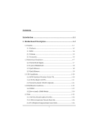
Description 1-2 1.1 Features 1-2 1.1.1 Hardware...1-2 1.1.2 BIOS ...1-6 1.1.3 Software...1-6 1.1.4 Accessories ...1-6 1.2 Motherboard Installation 1-7 1.2.1 System Block Diagram 1-7 1.2.2 Layout of Motherboard 1-8 1.2.3 Quick Reference 1-8 1.2.3 Quick Reference 1-9 1.3 CPU Installation 1-10 - Biostar M7TDE | M7TDE user's manual - Page 4
Contents 1.6 Connectors, Headers & Jumpers 1-17 1.6.1 Front Panel Connector: JPANEL1 1-18 1.6.2 ATX 20-pin Power Connector: JATXPWR1 1-20 1.6.3 ATX 12V Power Connector: JATXPWR2 1-20 1.6.4 AUX Power Connector: JAUXPWR1 1-20 1.6.5 Hard Disk Connectors: IDE1/IDE2 1-21 1.6.6 Floppy Disk Connector - Biostar M7TDE | M7TDE user's manual - Page 5
2-6 2.3 Advanced BIOS Features 2-9 2.4 Advanced Chipset Features 2-13 2.5 Integrated Peripherals 2-16 2.6 Power Management Setup 2-21 2.7 PnP/PCI Configurations 2-26 2.8 PC Health Status 2-29 2.9 Frequency Control 2-31 3. Trouble Shooting 3-1 iii - Biostar M7TDE | M7TDE user's manual - Page 6
of its predecessors, this motherboard continues the commitment of reliability compatibility with industry software and hardware standards. M7TDE Highlights: 8 Contains on board I/O facilities devices such as hard disks and CD-ROM Drives. 8 Supports the Intel Pentium 4® (Socket 478) processor, a - Biostar M7TDE | M7TDE user's manual - Page 7
of the Enhanced Mode Scaleable Bus Protocol. Intel Pentium ® 4 System Bus interrupt delivery. Supports system bus Dynamic Bus Inversion (DBI). Supports 32-bit system bus addressing. Speed Runing at 400 MHz Front Side Bus frequency. Supports up to 2 GHz CPU core speeds. The 33MHz 32 bit PCI - Biostar M7TDE | M7TDE user's manual - Page 8
one DDR-SDRAM channel, 64 wide (72b with ECC). − No support for DSx16 DIMMs. Shadow RAM − Motherboard is equipped with a memory controller providing shadow RAM and support for ROM BIOS. Green Functionality − Supports Award BIOS™ power management functionality. − Has a power down timer from - Biostar M7TDE | M7TDE user's manual - Page 9
1 Motherboard Description Built in IDE Facilities − Supports four IDE hard disk drives. − Supports PIO Mode 4, Master Mode, and high performance hard disk drives. − Supports disk transfer rates up to 100 MB/second. − Supports Ultra DMA 33, Ultra DMA 66, Ultra DMA 100 Bus Master Modes. − Supports - Biostar M7TDE | M7TDE user's manual - Page 10
a single AGP device (either a connector or on the motherboard). − Supports AGP 2.0 including 4X AGP data transfers and 2x/4x Fast Write protocol. − Supports only 1.5v AGP electricals. − High priority access support. − Hierarchical PCI configuration mechanism. Dimensions (Micro ATX form-factor - Biostar M7TDE | M7TDE user's manual - Page 11
Chapter 1 Motherboard Description 1.1.2 BIOS − AWARD legal BIOS. − Supports APM1.2. − Supports USB Function. − Supports ACPI. 1.1.3 Software Operating System − Offers the highest performance for Update. − USB Cable (Optional). − Rear I/O Panel for ATX Case (Optional). − Fully Setup Driver CD. 1-6 - Biostar M7TDE | M7TDE user's manual - Page 12
Chapter 1 Motherboard Description 1.2 Motherboard Installation 1.2.1 System Block Diagram Block Diagram VRM 9.0 478-Pin Socket Processor Pentium(R)4 Clock Term DATA DATA CTRL CTRL ADDR ADDR AGP 4X Interface MCH Brookdale - Biostar M7TDE | M7TDE user's manual - Page 13
Description 1.2.2 Layout of Motherboard Model No.M7TDE K/B & Mouse JKBMS1 JRJ45USB1 JATXPWR2 USB & LAN JCOM1 JPRNT1 Socket 478 JCFAN1 JDIMMVOLT COM1 DDR1 DDR2 Parallel Port COM2 JCOM2 JSPKR1 SP-OUT JGAME1 GAME Port - Biostar M7TDE | M7TDE user's manual - Page 14
Chapter 1 Motherboard Description 1.2.3 Quick Reference E DC B A Winbond I/O U LAN CHIP T S Socket 478 F G ROM1 82845 82801BA H I R DIMM1 Q DIMM2 JK L M A. Back Panel I/O Connectors N O P M. Secondary IDE Connector (IDE2) B. Front Audio Header ( - Biostar M7TDE | M7TDE user's manual - Page 15
Chapter 1 Motherboard Description 1.3 CPU Installation 1.3.1 0CPU Installation Procedure: Socket 478 Socket 478 CPU 1. Pull the lever sideways away from the socket then raise the lever up to - Biostar M7TDE | M7TDE user's manual - Page 16
Chapter 1 CPU Installation Layout Socket 478 Motherboard Description 1 JCFAN1 DIMM1 DIMM2 82845 LAN CHIP 82801BA LPC I/O ROM1 1.3.2 CPU Fan Header: JCFAN1 Pin No. 1 2 3 Assignment Ground +12V Sense 1 JSFAN1 1.3.3 System Fan Header: JSFAN1 ( - Biostar M7TDE | M7TDE user's manual - Page 17
Chapter 1 Motherboard Description 1.4 RAM Module Installation 1.4.1 DIMM DRAM Access Time: 2.5V Unbuffered/ Registered DDR SDRAM PC 200/266 Type required. DRAM Type: 64MB/ 128MB/ 256MB/ 512MB/ 1GB - Biostar M7TDE | M7TDE user's manual - Page 18
Chapter 1 Motherboard Description Total Memory Size (MB) 576 M 640 M 768 M 1024 M 1.512 G 1.064 G 1.128 G 1.256 G 1.512 G 2 G 1 DIMM 64 M 128 M 256 M 512 M 1G 64 M 128 M 256 M 512 M 1G 2 - Biostar M7TDE | M7TDE user's manual - Page 19
Chapter 1 Motherboard Description 1.4.2 How to install a DIMM Module Single Sided DIMM Double Sided DIMM 1. The DIMM socket has a " Plastic Safety Tab", and the DIMM memory module has - Biostar M7TDE | M7TDE user's manual - Page 20
and connect them to the system bus. Expansion slots are a means of adding or enhancing the motherboard's features and capabilities. With these efficient facilities, you can increase the motherboard's capabilities by adding hardware that performs tasks that are not part of the basic system. Socket - Biostar M7TDE | M7TDE user's manual - Page 21
in video facilities and therefore requires a video card for one of the expansion slots. Your monitor will attach directly to that video card. This motherboard supports video cards for PCI slots, but it is also equipped with an Accelerated Graphics Port (AGP). An AGP card will take advantage of AGP - Biostar M7TDE | M7TDE user's manual - Page 22
Chapter 1 Motherboard Description 1.6 Connectors, Headers & Jumpers The connectors, headers and jumpers introduced below provide you lots of capabilities such as power supply, front panel signal revelation, IDE - Biostar M7TDE | M7TDE user's manual - Page 23
Button POWER LED POWER Button IrDA Connector Speaker Connector An offboard speaker can be installed on the motherboard as a manufacturing option. It can be connected to the motherboard at the front panel connector. The speaker (onboard or offboard) provides error beep code information during the - Biostar M7TDE | M7TDE user's manual - Page 24
switch is usually open, and when it is closed, it will cause the motherboard to reset and run the POST (Power On Self Test). Power LED Connector Advanced Power Management) must be enabled in the system BIOS, and the APM driver must be loaded. Power Button This connector can be attached to a front - Biostar M7TDE | M7TDE user's manual - Page 25
power button on-board. Using the ATX power supply, function such as Soft Power Off is supported on this motherboard. This power connector supports instant power-on functionality, which means that the system will boot up instantly when the power connector is inserted on the board. PIN Assignment - Biostar M7TDE | M7TDE user's manual - Page 26
controller must be set to slave mode. 1.6.6 Floppy Disk Connector: FDD1 The motherboard provides a standard floppy disk connector (FDC) that supports 360K, 720K, 1.2M, 1.44M and 2.88M floppy disk types. This connector supports the provided floppy drive ribbon cables. 1.6.7 Wake On LAN Header: JWOL1 - Biostar M7TDE | M7TDE user's manual - Page 27
Chapter 1 Motherboard Description 1.6.8 Clear CMOS Jumper: JCMOS1 JCMOS1 1 3 1-2 Closed 1 3 2-3 Closed Assignment Normal Operation (default) Clear CMOS Data Remove AC power line JCMOS1 (2-3) closed Wait five seconds JCMOS1 (1-2) - Biostar M7TDE | M7TDE user's manual - Page 28
COM1 Rj45(Optional) JCOM1 COM2 JCOM2 Speaker Line In Mic Out In JSPKR1 JLIN1 JMIC1 1.7.1 PS/2 Mouse / Keyboard Connector: JKBMS1 The motherboard provides a standard PS/2 mouse / Keyboard mini DIN connector for attaching a PS/2 mouse. You can plug a PS/2 mouse / Keyboard directly into this - Biostar M7TDE | M7TDE user's manual - Page 29
Description 1.7.2 USB & LAN Connector: JRJ45USB1 The motherboard provides an OHCI (Open Host Controller Interface) Universal Serial Bus Roots for attaching USB devices such as: keyboard, mouse and other USB devices. You can - Biostar M7TDE | M7TDE user's manual - Page 30
Chapter 1 Motherboard Description 1.7.3 Serial and Parallel Interface Ports This system is equipped with two serial ports and one parallel port. Both types of interface ports will be - Biostar M7TDE | M7TDE user's manual - Page 31
Chapter 1 Motherboard Description Connectivity The serial ports can be used in many ways, and it may be necessary to become familiar with the pinout diagram. The following - Biostar M7TDE | M7TDE user's manual - Page 32
Chapter 1 Motherboard Description 1.7.3.2 Parallel Interface Port: JPRNT1 Unlike the serial ports, parallel interface port has been standardized, and it should not present any difficulty interfacing peripherals of - Biostar M7TDE | M7TDE user's manual - Page 33
Chapter 1 Motherboard Description 1.7.4 Game (Joystick/MIDI) Port Connector: JGAME1 This connector allows you to connect a joystick or game pad for playing computer games. Also, you may play - Biostar M7TDE | M7TDE user's manual - Page 34
Chapter 1 1.7.6 Audio Subsystem Motherboard Description Socket 478 DIMM1 DIMM2 JTAD1 LAN JAUDIO1 CHIP JCDIN1 LPC I/O 82845 82801BA ROM1 1-29 - Biostar M7TDE | M7TDE user's manual - Page 35
Chapter 1 Motherboard Description 1.7.6.1 CD-ROM Audio-In Header: JCDIN1 Pin No. 1 2 3 4 Assignment Left Channel Input Ground Ground Right Channel Input 1.7.6.2 Front Audio Header: JAUDIO1 Pin No. 1 3 5 7 9 Assignment - Biostar M7TDE | M7TDE user's manual - Page 36
-tuning of the chipset controlling the entire system. The rest of this manual is intended to guide you through the process of configuring your system using Setup. Plug and Play Support These AWARD BIOS supports the Plug and Play Version 1.0A specification. ESCD (Extended System Configuration Data - Biostar M7TDE | M7TDE user's manual - Page 37
Version 2.1 of the Intel PCI (Peripheral Component Interconnect) local bus specification. DRAM Support DDR SDRAM (Double Data Rate Synchronous DRAM) are supported. Supported CPUs This AWARD BIOS supports the Intel Pentium ® 4 CPU. Using Setup In general, you use the arrow keys to highlight items - Biostar M7TDE | M7TDE user's manual - Page 38
the arrow keys to select among the items and press to accept and enter the sub-menu. !! WARNING !! The information about BIOS defaults on manual (Figure 1,2,3,4,5,6,7,8,9) is just for reference, please refer to the BIOS installed on board, for update information. Figure 1. Main Menu 2-3 - Biostar M7TDE | M7TDE user's manual - Page 39
may cause CPU or M/B damage!) Load Optimized Defaults This selection allows you to reload the BIOS when the system is having problems particularly with the boot sequence. These configurations are factory settings optimized for this system. A confirmation message will be displayed before defaults - Biostar M7TDE | M7TDE user's manual - Page 40
Chapter 2 BIOS Setup Set Supervisor Password Setting the supervisor password will prohibit everyone except the supervisor from making changes using the CMOS Setup Utility. You will be prompted with to enter a password. Set User Password If the Supervisor Password is not set, then the User - Biostar M7TDE | M7TDE user's manual - Page 41
Chapter 2 BIOS Setup 2.2 Standard CMOS Features The items in Standard CMOS Setup Menu are divided into 10 categories. Each category includes no, one or more than one setup items. Use the arrow keys to highlight the item and then use the or keys to select the value you want in each - Biostar M7TDE | M7TDE user's manual - Page 42
Chapter 2 BIOS Setup Main Menu Selections This table shows the selections that you can make on the Main Menu. Item Options Description Date mm : dd : yy Set the system date. Note that the 'Day' automatically changes when you set the date. Time hh : mm : ss Set the system internal clock. - Biostar M7TDE | M7TDE user's manual - Page 43
Chapter 2 BIOS Setup Item Halt On Base Memory Extended Memory Total Memory Options All Errors No Errors All, but Keyboard All, but Diskette All, but Disk/ Key N/A N/A N/A Description Select the situation in which you want the BIOS to stop the POST process and notify you. Displays the amount of - Biostar M7TDE | M7TDE user's manual - Page 44
Chapter 2 BIOS Setup 2.3 Advanced BIOS Features Figure 3. Advanced BIOS Setup Virus Warning This option allows you to choose the VIRUS Warning feature that is used to protect the IDE Hard Disk boot sector. If this function is enabled and an attempt is made to write to the boot sector, BIOS will - Biostar M7TDE | M7TDE user's manual - Page 45
Chapter 2 BIOS Setup CPU L1 & L2 Cache This option allows you to enable or disable the CPU L1 & L2 Cache which improve performance. The Choices: Enabled (default), Disabled. Quick Power On Self Test Enabling this option will cause an abridged version of the Power On Self-Test (POST) to execute - Biostar M7TDE | M7TDE user's manual - Page 46
the BIOS to the operating system. The Choices: Enabled (default), Disabled. MPS Version Control For OS The BIOS supports version 1.1 and 1.4 of the Intel multiprocessor specification. Select version supported by the operation system running on this computer. The Choices: 1.4 (default), 1.1. 2-11 - Biostar M7TDE | M7TDE user's manual - Page 47
Chapter 2 BIOS Setup OS Select For DRAM > 64MB A choice other than Non-OS2 is only used for OS2 systems with memory exceeding 64MB. The Choices: Non-OS2 (default), OS2. Report No FDD For WIN 95w Whether report no FDD for Win 95 or not. The Choices: No (default), Yes. 2-12 - Biostar M7TDE | M7TDE user's manual - Page 48
Chapter 2 BIOS Setup 2.4 Advanced Chipset Features This submenu allows you to configure the specific features of the chipset installed on your system. This chipset manage bus speeds and access to system memory resources, such as DRAM and external cache. It also coordinates communications with the - Biostar M7TDE | M7TDE user's manual - Page 49
performance. This field applies only when synchronous DRAM is installed in the system. The Choices: 3 (default), 2. DRAM Data Integrity Mode This item select supported ECC or Non-ECC for DRAM. The Choices: Non-ECC (default), ECC. Memory Frequency For The default is Auto. Dram Read Thermal Mgmt The - Biostar M7TDE | M7TDE user's manual - Page 50
Choices: Disabled (default), Enabled. Delayed Transaction The chipset has an embedded 32-bit posted write buffer to support delay transactions cycles. Select Enabled to support compliance with PCI specification version 2.1. The Choices: Enabled (default), Disabled. AGP Aperture Size (MB) Select the - Biostar M7TDE | M7TDE user's manual - Page 51
Chapter 2 2.5 Integrated Peripherals Figure 5. Integrated Peripherals BIOS Setup Onboard LAN Boot ROM This item allows you to enable or disable Onboard LAN Boot ROM. The Choices: Enabled (default), Disabled. Onboard PCI LAN This item allows you to enable or disable Onboard PCI LAN. The Choices: - Biostar M7TDE | M7TDE user's manual - Page 52
in your system. As well, your operating environment requires a DMA driver (Windows 95 OSR2 or a third party IDE bus master driver). If your hard drive and your system software both support Ultra DMA/100, select Auto to enable BIOS support. The Choices: Auto (default), Disabled. IDE HDD Block Mode - Biostar M7TDE | M7TDE user's manual - Page 53
(USB) controller and you have USB peripherals. The Choices: Enabled (default), Disabled. USB Keyboard Support The default value is Disabled. Enabled Disabled (default) Enable USB Keyboard Support. Disable USB Keyboard Support. AC97 Audio/ Modem This item allows you to decide to enable/ disable to - Biostar M7TDE | M7TDE user's manual - Page 54
Using Parallel Port as Enhanced Parallel Port. ECP Using Parallel Port as Extended Capabilities Port. ECP+EPP Using Parallel Port as ECP & EPP mode. Normal Supports EPP or ECP mode. 2-19 - Biostar M7TDE | M7TDE user's manual - Page 55
Chapter 2 EPP Mode Select Select EPP port type 1.7 or 1.9. The Choices: EPP1.7 (default), EPP1.9. ECP Mode Use DMA Select a DMA Channel for the port. The Choices: 3 (default), 1. Game Port Address Game Port I/O Address. The Choices: 201 (default), 209, Disabled. BIOS Setup Midi Port Address Midi - Biostar M7TDE | M7TDE user's manual - Page 56
Chapter 2 BIOS Setup 2.6 Power Management Setup The Power Management Setup Menu allows you to configure your system to utilize energy conservation and power up/power down features. Figure 6. Power Management Setup ACPI function This item displays the status of the Advanced Configuration and Power - Biostar M7TDE | M7TDE user's manual - Page 57
Chapter 2 BIOS Setup ACPI Suspend Type The item allows you to select the suspend type under the ACPI operating system. The Choices: S1 (POS) (default) Power on Suspend S3 (STR) Suspend to RAM S1 & S3 Power Management This category allows you to select the type (or degree) of power saving and - Biostar M7TDE | M7TDE user's manual - Page 58
and horizontal synchronization ports and write blanks to the video buffer. Blank Screen This option only writes blanks to the video buffer. DPMS Support (default) Initial display power management signaling. Video Off In Suspend This determines the manner in which the monitor is blanked. The Choices - Biostar M7TDE | M7TDE user's manual - Page 59
power is restored to a system that had lost power previously without any subsequent manual intervention. There are 3 sources that provide current to the CMOS area that retains these Power-On instructions; the motherboard battery (3V), the Power Supply (5VSB), and the Power Supply (3.3V). While AC - Biostar M7TDE | M7TDE user's manual - Page 60
off state. The Choices: Disabled (default), Enabled. WakeUp On LAN To use this function, you need a LAN add-on card which support power on function. It should also support the wake-up on LAN jumper. The Choices: Disabled (default), Enabled. Resume by Alarm This function is for setting date and time - Biostar M7TDE | M7TDE user's manual - Page 61
Chapter 2 BIOS Setup 2.7 PnP/PCI Configurations This section describes configuring the PCI bus system. PCI, or Personal Computer Interconnect, is a system which allows I/O devices to operate at speeds nearing the speed of the CPU itself uses when communicating with its own special components. This - Biostar M7TDE | M7TDE user's manual - Page 62
BIOS Setup Reset Configuration Data The system BIOS supports the PnP feature which requires the system to record to the "Disabled" mode. The above settings will be shown on the screen only if "Manual" is chosen for the resources controlled by function. Legacy is the term, which signifies that a - Biostar M7TDE | M7TDE user's manual - Page 63
Chapter 2 BIOS Setup PCI / VGA Palette Snoop Choose Disabled or Enabled. Some graphic controllers which are not VGA compatible take the output from a VGA controller and map it to their display as a way to provide boot information and VGA compatibility. However, the color information coming from - Biostar M7TDE | M7TDE user's manual - Page 64
Chapter 2 2.8 PC Health Status Figure 8. PC Health Status BIOS Setup CPU Warning Temperature The item will prevent CPU from overheating. The Choices: Disabled (default), 50OC/122OF, 53OC/127OF, 56OC/133OF, 60OC/140OF, 63OC/145OF, 66OC/151OF, 70OC/158OF. Current CPU1 Temperature Show you the - Biostar M7TDE | M7TDE user's manual - Page 65
Chapter 2 BIOS Setup Current CPUFAN Speed This field displays the current CPUFAN speed. CPU Vcore/AGP Voltage/+3.3V/+-5V/+-12V/VBAT(V)/5VSB(V) Detect the system's voltage status automatically. Shutdown Temperature This item allows you to set up the CPU shutdown Temperature. This item only - Biostar M7TDE | M7TDE user's manual - Page 66
Chapter 2 2.9 Frequency Control Figure 9. Frequency Control BIOS Setup CPU Clock Ratio This item allows you to select the CPU Ratio. Auto Detect DIMM/PCI Clk This item allows you to enable / disable auto Detect DIMM/PCI Clock. The Choices: Enabled (default), Disabled. Spread Spectrum This item - Biostar M7TDE | M7TDE user's manual - Page 67
Chapter 2 BIOS Setup Clock by Slight Adjust This item allows you to adjust CPU frequency when "Slight Adjust" enable. The Choices: Disabled (default), Enabled. CPU Clock This item allows you to select CPU Clock . If unfortunately, the system's frequency that you are selected is not functioning, - Biostar M7TDE | M7TDE user's manual - Page 68
Trouble Shooting 3. Trouble Shooting PROBLEM . Power supply failure. Power cable and wall Contact technical support. socket are OK, but system is still dead. Faulty Memory DIMM is partially dislodged from the slot on the motherboard. Turn off computer. Take Using even pressure on cover - Biostar M7TDE | M7TDE user's manual - Page 69
Chapter 3 Trouble Shooting PROBLEM System does not boot from hard disk drive, can be Damaged hard disk or disk controller. Format hard disk; if Contact technical unable to do so the hard support. disk may be defective. Hard disk directory or FAT is scrambled. Run the FDISK program, format the - Biostar M7TDE | M7TDE user's manual - Page 70
3 Trouble Shooting PROBLEM Error hard drive. Re-install all saved data when completed. PROBLEM Screen message says "Invalid Configuration" or "CMOS Failure No power to monitor. Monitor not connected to computer. PROBLEM DIAGNOSIS SOLUTION Check the power connectors to monitor and to system - Biostar M7TDE | M7TDE user's manual - Page 71
Chapter 3 Trouble Shooting No screen. PROBLEM PROBABLE CAUSE Memory problem. Computer virus. DIAGNOSIS SOLUTION Reboot computer. Reinstall memory, make sure that all memory modules are installed in correct sockets. Use anti-virus programs to detect and clean viruses. PROBLEM Screen goes blank - Biostar M7TDE | M7TDE user's manual - Page 72
Chapter 3 Trouble Shooting No color on screen. PROBLEM PROBABLE CAUSE Faulty Monitor. CMOS incorrectly set up. DIAGNOSIS SOLUTION If possible, connect monitor to another system. If no color replace monitor. Call technical support. C: drive failure. PROBLEM PROBABLE CAUSE Hard drive cable - Biostar M7TDE | M7TDE user's manual - Page 73
Chapter 3 Trouble Shooting PROBLEM Missing operating system on hard drive. PROBABLE CAUSE CMOS setup has been changed. DIAGNOSIS SOLUTION Run setup and select correct drive type. PROBLEM Certain keys do not function. PROBABLE CAUSE Keys jammed or defective. DIAGNOSIS SOLUTION Replace - Biostar M7TDE | M7TDE user's manual - Page 74
01/10/2002 MADE IN TAIWAN R.O.C.
-
 1
1 -
 2
2 -
 3
3 -
 4
4 -
 5
5 -
 6
6 -
 7
7 -
8
-
9
-
10
-
11
-
12
-
13
-
14
-
15
-
16
-
17
-
18
-
19
-
20
-
21
-
22
-
23
-
24
-
25
-
26
-
27
-
28
-
29
-
30
-
31
-
32
-
33
-
34
-
35
-
36
-
37
-
38
-
39
-
40
-
41
-
42
-
43
-
44
-
45
-
46
-
47
-
48
-
49
-
50
-
51
-
52
-
53
-
54
-
55
-
56
-
57
-
58
-
59
-
60
-
61
-
62
-
63
-
64
-
65
-
66
-
67
-
68
-
69
-
70
-
71
-
72
-
73
-
74
 |
 |

M7TDE
Federal Communications Commission
(F.C.C.) Statement
This device complies with Part 15 of the FCC Rules. Operation of this device is
subject to the following two conditions: (1) this device may not cause harmful
interference, and (2) this device must accept any interference received, including
interference that may cause undesired operation.
Accessories: This device has been tested and found to comply with the limits of a
Class B digital device; the accessories associated with this equipment are as
follows:
1. Shielded serial cable. (Can be obtained from multiple retail outlets)
2. Shielded printer cable. (Can be obtained from multiple retail outlets)
3. Shielded video cable. (Can be obtained from multiple retail outlets)
4. Shielded power cord. (Provided by manufacturer)
These accessories are required to ensure compliance with FCC Rules. It is the
responsibility of the user to provide and use these accessories properly.
This equipment has been tested and found to comply with the limits of a Class B
digital device, pursuant of Part 15 of the FCC Rules. These limits are designed to
provide reasonable protection against harmful interference in a residential
installation. This equipment generates, uses and radiates radio frequency energy
and, if you did not installed and used in accordance with the instructions, may
cause harmful interference in the radio communications. There is no guarantee
that interference will not occur in a particular installation. If this equipment does
cause harmful interference to radio or television reception, which can be
determined by turning the equipment off and on, you are encouraged to try to
correct the interference by one or more of the following measures:
1. Reorient / relocate the receiving antenna.
2. Increase the separation between the equipment and the receiver.
3. Connect the equipment into an outlet from a circuit where the receiver is
connect.
4. Consult the dealer or an experienced radio/TV technician for help.
Caution: Changes or modifications that is not expressly approved by the
manufacturer could void the user’s authority to operate the equipment.