Biostar M7TDE M7TDE user's manual - Page 26
Hard Disk Connectors: IDE1/IDE2, 6.6 Floppy Disk Connector: FDD1, 6.7 Wake On LAN Header: JWOL1
 |
View all Biostar M7TDE manuals
Add to My Manuals
Save this manual to your list of manuals |
Page 26 highlights
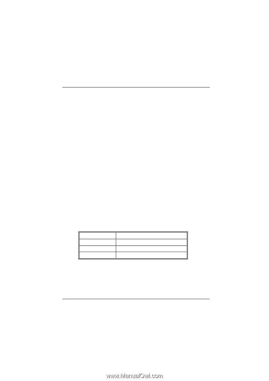
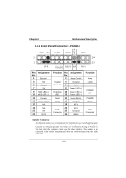
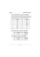
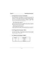
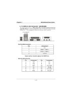
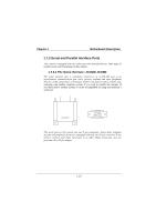
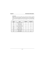
Chapter 1 Motherboard Description 1.6.5 Hard Disk Connectors: IDE1/IDE2 The motherboard has a 32-bit Enhanced PCI IDE Controller that provides PIO Mode 0~4, Bus Master, and Ultra DMA / 33, Ultra DMA / 66,Ultra DMA / 100 functionality. It has two HDD connectors IDE1 (primary) and IDE2 (secondary). You can connect up to four hard disk drives, a CD-ROM, a 120MB Floppy (reserved for future BIOS) and other devices to IDE1 and IDE2. These connectors support the IDE hard disk cable provided. • IDE1 (Primary IDE Connector) The first hard drive should always be connected to IDE1. IDE1 can connect a Master and a Slave drive. You must configure the second hard drive on IDE1 to Slave mode by setting the jumper accordingly. • IDE2 (Secondary IDE Connector) The IDE2 controller can also support a Master and a Slave drive. It is configuration is similar to IDE1. The second drive on this controller must be set to slave mode. 1.6.6 Floppy Disk Connector: FDD1 The motherboard provides a standard floppy disk connector (FDC) that supports 360K, 720K, 1.2M, 1.44M and 2.88M floppy disk types. This connector supports the provided floppy drive ribbon cables. 1.6.7 Wake On LAN Header: JWOL1 Pin No. 1 2 3 Assignment 5V SB Ground Wake up 1-21
-
 1
1 -
2
-
3
-
4
-
5
-
6
-
7
-
8
-
9
-
10
-
11
-
12
-
13
-
14
-
15
-
16
-
17
-
18
-
19
-
20
-
 21
21 -
 22
22 -
 23
23 -
 24
24 -
 25
25 -
 26
26 -
 27
27 -
 28
28 -
 29
29 -
 30
30 -
 31
31 -
32
-
33
-
34
-
35
-
36
-
37
-
38
-
39
-
40
-
41
-
42
-
43
-
44
-
45
-
46
-
47
-
48
-
49
-
50
-
51
-
52
-
53
-
54
-
55
-
56
-
57
-
58
-
59
-
60
-
61
-
62
-
63
-
64
-
65
-
66
-
67
-
68
-
69
-
70
-
71
-
72
-
73
-
74
 |
 |