Biostar M7VIG PRO D M7VIG Pro D user's manual - Page 6
Package contents, How to setup Jumper - drivers
 |
View all Biostar M7VIG PRO D manuals
Add to My Manuals
Save this manual to your list of manuals |
Page 6 highlights
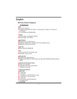
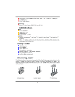
1 floppy port supports 2 FDDs with 360K, 720K, 1.2M, 1.44M and 2.88Mbytes. 2 USB2.0 ports. 1 front audio header. Dimensions Micro ATX Form Factor: 21.3 X 24.4cm (W X L) B. BIOS & Software BIOS Award legal Bios. Supports APM1.2. Supports ACPI. Supports USB Function. Software Supports WarpspeederTM, 9th TouchTM, FLASHER™, WinFlasherTM and StudioFun!TM (optional). Offers the highest performance for Windows 98 SE, Windows 2000, Windows Me, Windows XP, SCO UNIX etc. Package contents HDD Cable X1 FDD Cable X1 User's Manual X1 USB Cable X1 (optional) Rear I/O Panel for ATX Case X1 (optional) Fully Setup Driver CD X1 S/PDIF Cable X1 (optional) How to setup Jumper The illustration shows how jumpers are setup. When the Jumper cap is placed on pins, the jumper is "close". If no jumper cap is placed on the pins, the jumper is "open". The illustration shows a 3-pin jumper whose pin 1and 2 are "close" when jumper cap is placed on these 2 pins. Jumper close Jumper open 4 Pin 1-2 close
-
 1
1 -
 2
2 -
 3
3 -
 4
4 -
 5
5 -
 6
6 -
 7
7 -
 8
8 -
 9
9 -
 10
10 -
 11
11 -
 12
12 -
13
-
14
-
15
-
16
-
17
-
18
-
19
-
20
-
21
-
22
-
23
-
24
-
25
-
26
-
27
-
28
-
29
-
30
-
31
-
32
-
33
-
34
-
35
-
36
-
37
-
38
-
39
-
40
-
41
-
42
-
43
-
44
-
45
-
46
-
47
-
48
-
49
-
50
 |
 |
