Biostar NF325-A7 Nf325-A7 BIOS setup guide - Page 24
ECP Mode Use DMA - windows 7 drivers
 |
View all Biostar NF325-A7 manuals
Add to My Manuals
Save this manual to your list of manuals |
Page 24 highlights
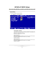
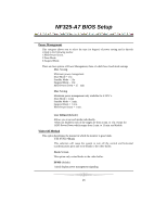
NF325-A7 BIOS Setup UART Mode Select This item allows you to determine which Infrared (IR) function of onboard I/O chip. The Choices: Normal(default), ASKIR, IrDA, SCR . UR2 Duplex Mode Select the value required by the IR device connected to the IR port. Full-duplex mode permits simultaneous two-direction transmission. Half-duplex mode permits transmission in one direction only at a time. The Choices: Half (default), Full. Onboard Parallel Port This item allows you to determine access onboard parallel port controller with which I/O Address. The Choices: 378/IRQ7 (default), 278/IRQ5, 3BC/IRQ7, Disabled. Parallel Port Mode The default value is SPP. The Choices: SPP (Default) Using Parallel Port as Standard Printer Port. EPP Using Parallel Port as Enhanced Parallel Port. ECP Using Parallel Port as Extended Capabilities Port. ECP+EPP Using Parallel Port as ECP & EPP mode. ECP Mode Use DMA Select ECP port type 1 or 3. The Choices: 3 (default), 1. Primary/Secondary/Master/Slave PIO The IDE PIO (Programmed Input / Output) fields let you set a PIO mode (0-4) for each of the IDE devices that the onboard IDE interface supports. Modes 0 to 4 will increase performance progressively. In Auto mode, the system automatically determines the best mode for each device. The Choices: Auto (default), Mode0, Mode1, Mode2, Mode3, and Mode4. Primary/Secondary/Master/Slave UDMA Ultra DMA/100 functionality can be implemented if it is supported by the IDE hard drives in your system. As well, your operating environment requires a DMA driver (Windows 95 OSR2 or a third party IDE bus master driver). If your hard drive and your system software both support Ultra DMA/100, select Auto to enable BIOS support. The Choices: Auto (default), Disabled. 23
-
 1
1 -
2
-
3
-
4
-
5
-
6
-
7
-
8
-
9
-
10
-
11
-
12
-
13
-
14
-
15
-
16
-
17
-
18
-
 19
19 -
 20
20 -
 21
21 -
 22
22 -
 23
23 -
 24
24 -
 25
25 -
 26
26 -
 27
27 -
 28
28 -
 29
29 -
30
-
31
-
32
-
33
-
34
-
35
 |
 |
